Toyota Venza: Installation
INSTALLATION
PROCEDURE
1. INSTALL NO. 3 PARKING BRAKE CABLE ASSEMBLY
(a) Install the No. 3 parking brake cable assembly with the bolt and 4 nuts.
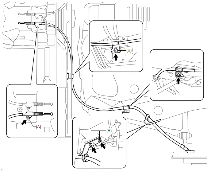
Torque:
Nut (A) :
5.4 N·m {55 kgf·cm, 48 in·lbf}
Nut (B) :
6.0 N·m {61 kgf·cm, 53 in·lbf}
Bolt :
6.0 N·m {61 kgf·cm, 53 in·lbf}
|
(b) Install the No. 3 parking brake cable assembly to the backing plate with the 2 bolts. Torque: 8.0 N·m {82 kgf·cm, 71 in·lbf} |
|
.png)
2. INSTALL NO. 2 PARKING BRAKE CABLE ASSEMBLY
HINT:
Use the same procedure as for the No. 3 parking brake cable assembly.
3. INSTALL NO. 2 PARKING BRAKE SHOE ASSEMBLY WITH PARKING BRAKE SHOE LEVER
(a) Refer to the instructions for Installation of the No. 2 parking brake shoe
assembly with parking brake shoe lever (See page
.gif) ).
).
4. INSTALL REAR WHEEL
Torque:
103 N·m {1050 kgf·cm, 76 ft·lbf}
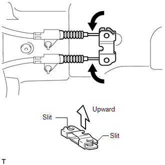
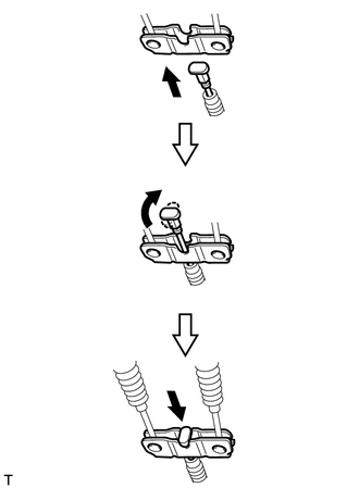
5. INSTALL PARKING BRAKE EQUALIZER
|
(a) Connect the No. 2 parking brake cable assembly and No. 3 parking brake cable assembly to the parking brake equalizer to install it. NOTICE: The slits of the parking brake equalizer face upward. |
|
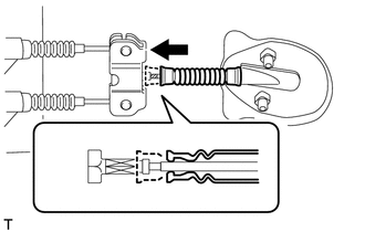
6. INSTALL NO. 4 PARKING BRAKE CABLE ASSEMBLY
|
(a) Install the No. 4 parking brake cable assembly with the 2 bolts. Torque: 21 N·m {214 kgf·cm, 15 ft·lbf} |
|
.png)
|
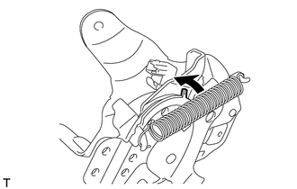
(b) Connect the No. 4 parking brake cable assembly to the parking brake equalizer as shown in the illustration. |
|
|
(c) Slide the rubber boot to engage it as shown in the illustration. |
|
7. INSTALL NO. 1 PARKING BRAKE CABLE ASSEMBLY
(a) Pass the No. 1 parking brake cable assembly through the parking brake pedal assembly.
|
(b) Install a new clip to the No. 1 parking brake cable assembly. |
|
.png)
|
(c) Depress the parking brake pedal. |
|
.png)
|
(d) Bend the parking brake pedal claw to hold the No. 1 parking brake cable assembly. |
|
(e) Release the parking brake pedal.
8. INSTALL PARKING BRAKE PEDAL ASSEMBLY
HINT:
Refer to the instructions for Installation of the parking brake pedal assembly
(See page ).
9. BED IN PARKING BRAKE SHOES TO DISCS
10. ADJUST PARKING BRAKE SHOE CLEARANCE AND PARKING BRAKE PEDAL TRAVEL
11. INSPECT BRAKE WARNING LIGHT
 Removal
REMOVAL
PROCEDURE
1. REMOVE PARKING BRAKE PEDAL ASSEMBLY
HINT:
Refer to the instructions for Removal of the parking brake pedal assembly (See
page ).
2. REMOVE NO. 1 PARKING BRAKE CABLE ASSEMB ...

Other materials about Toyota Venza:
Receiver Error (C2176/76)
DESCRIPTION
The signals are transmitted to the tire pressure warning antenna and receiver
on the body as radio waves and then sent to the tire pressure warning ECU.
DTC No.
DTC Detection Condition
Trouble Area
...
Terminals Of Ecu
TERMINALS OF ECU
1. CHECK AWD CONTROL ECU
(a) Measure the voltage and resistance of the connector.
Terminal No. (Symbol)
Terminal Description
Condition
Specified Condition
14 (CANH) - 16 (CANL)
...
Interior lights list
Your Toyota is equipped with the illuminated entry system to assist in entering
the vehicle. Due to the function of the system, the lights shown in the following
illustration automatically turn on/off according to the presence of the electronic
key (vehi ...

0.1345