Toyota Venza: Components
COMPONENTS
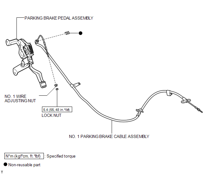
ILLUSTRATION
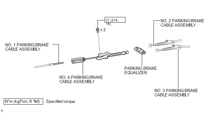
ILLUSTRATION
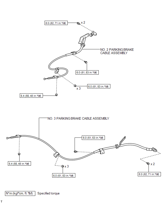
ILLUSTRATION

 Removal
REMOVAL
PROCEDURE
1. REMOVE PARKING BRAKE PEDAL ASSEMBLY
HINT:
Refer to the instructions for Removal of the parking brake pedal assembly (See
page ).
2. REMOVE NO. 1 PARKING BRAKE CABLE ASSEMB ...
Other materials about Toyota Venza:
Intuitive parking assist
The distance from your vehicle to nearby obstacles when parallel parking or
maneuvering into a garage is measured by the sensors and communicated via the multi-information
display and a buzzer.
Always check the surrounding area when using this system.
&n ...
AWD Warning Light Remains ON
DESCRIPTION
The AWD control ECU is connected to the combination meter via the CAN communication
system.
If the AWD control ECU stores any DTCs which are related to the active torque
control 4WD system, the AWD warning light comes on in the combination me ...
Problem Symptoms Table
PROBLEM SYMPTOMS TABLE
HINT:
Use the table below to help determine the cause of problem symptoms.
If multiple suspected areas are listed, the potential causes of the symptom
are listed in order of probability in the "Suspected Area" ...

0.1164