Toyota Venza: Transponder Key Ecu
Components
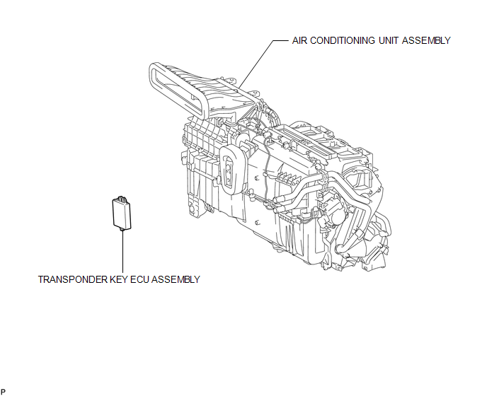
COMPONENTS
ILLUSTRATION
Removal
REMOVAL
PROCEDURE
1. REMOVE AIR CONDITIONING UNIT ASSEMBLY
HINT:
Refer to the procedure up to Remove Air Conditioning Unit Assembly (See page
.gif) ).
).
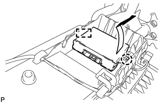
2. REMOVE TRANSPONDER KEY ECU ASSEMBLY
|
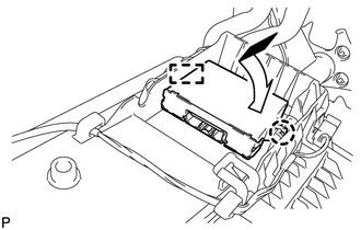
(a) Disengage the claw and guide and remove the transponder key ECU assembly. |
|
Installation
INSTALLATION
PROCEDURE
1. INSTALL TRANSPONDER KEY ECU ASSEMBLY
|
(a) Engage the guide and claw and install the transponder key ECU assembly. |
|
2. INSTALL AIR CONDITIONING UNIT ASSEMBLY
HINT:
Refer to the procedure from Install Air Conditioning Unit Assembly (See page
.gif) ).
).
3. REGISTER KEY
NOTICE:
When replacing the transponder key ECU assembly, perform initialization (See
page ).
 Transponder Key Amplifier
Components
COMPONENTS
ILLUSTRATION
Removal
REMOVAL
PROCEDURE
1. REMOVE FRONT DOOR SCUFF PLATE
2. REMOVE COWL SIDE TRIM SUB-ASSEMBLY
3. REMOVE LOWER NO. 1 INSTRUMENT PANEL FINISH PA ...
Other materials about Toyota Venza:
Moon roof
Use the overhead switches to open, close, and tilt the moon roof up and down.
- Opening and closing
1. Open
The moon roof stops slightly before the fully open position to reduce wind noise.
Move the switch backward again to fully open.
2. Close ( ...
Transmission Fluid Pressure Sensor / Switch "E" Circuit Low (P0989,P0990)
DESCRIPTION
ATF pressure switch No. 3 is installed in the lock-up solenoid ATF output passage
and is used to detect a malfunction in the lock-up solenoid.
DTC No.
DTC Detection Condition
Trouble Area
P0989
...
Control Module Communication Bus OFF (U0073/86,U0100/85,U0129/83)
DESCRIPTION
The AWD control ECU inputs the signals sent from the ECM and skid control
ECU via the CAN communication system.
When DTCs indicating a CAN communication system malfunction are output,
repair the CAN communication system before r ...

0.161