Toyota Venza: Components
COMPONENTS
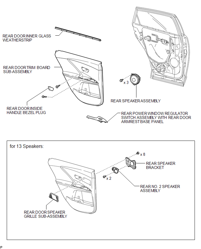
ILLUSTRATION

 Removal
REMOVAL
PROCEDURE
1. DISCONNECT CABLE FROM NEGATIVE BATTERY TERMINAL
CAUTION:
Wait at least 90 seconds after disconnecting the cable from the negative (-)
battery terminal to disable the SRS sys ...
Other materials about Toyota Venza:
Automatic High Beam
The Automatic High Beam uses an in-vehicle camera sensor to assess the brightness
of streetlights, the lights of oncoming and preceding vehicles, etc., and automatically
turns high beam on or off as necessary.
- Activating the Automatic High Beam sy ...
Precaution
PRECAUTION
1. NOTICE FOR INITIALIZATION:
NOTICE:
When disconnecting the cable from the negative (-) battery terminal, initialize
the following systems after the cable is reconnected.
System Name
See Procedure
Back D ...
Removal
REMOVAL
PROCEDURE
1. DISCHARGE FUEL SYSTEM PRESSURE
HINT:
(See page ).
2. DISCONNECT CABLE FROM NEGATIVE BATTERY TERMINAL
CAUTION:
When disconnecting the cable, some systems need to be initialized after the cable
is reconnected (See page ).
3. REMO ...

0.1376