Toyota Venza: Installation
INSTALLATION
CAUTION / NOTICE / HINT
HINT:
- Use the same procedure for the RH side and LH side.
- The procedure listed below is for the LH side.
PROCEDURE
1. INSTALL REAR AIRBAG SENSOR
(a) Check that the ignition switch is off.
(b) Check that the cable is disconnected from the negative (-) battery terminal.
CAUTION:
Wait at least 90 seconds after disconnecting the cable from the negative (-) battery terminal to disable the SRS system.
|
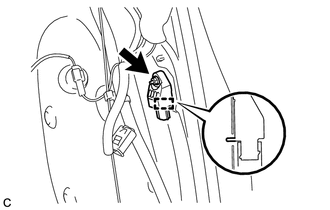
(c) Insert the pin (stopper) into the body hole and install the rear airbag sensor with the nut. Torque: 9.0 N·m {92 kgf·cm, 80 in·lbf} NOTICE:
|
|
(d) Connect the connector to the rear airbag sensor assembly.
NOTICE:
When connecting the airbag connector, take care not to damage the airbag wire harness.
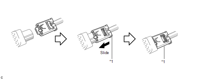
(1) Connect the connector as shown in the illustration (when locking, make sure that the outer connector locking sleeve returns to its original position and a click sound can be heard).
 Text in Illustration
|
*1 |
Outer Connector Locking Sleeve |
- |
- |
HINT:
When connected, the outer connector locking sleeve will slide. Be sure not to hold the outer connector locking sleeve while connecting, as it may result in an insecure fit.
(e) Check that there is no looseness in the installation parts of the rear airbag sensor.
2. INSTALL DECK TRIM SIDE PANEL ASSEMBLY
.gif)
3. CONNECT REAR SEAT OUTER BELT ASSEMBLY
4. INSTALL REAR DOOR OPENING TRIM WEATHERSTRIP
5. INSTALL REAR DOOR SCUFF PLATE
6. INSTALL LUGGAGE HOLD BELT STRIKER ASSEMBLY
7. INSTALL RECLINING REMOTE CONTROL BEZEL
8. INSTALL REAR FLOOR FINISH PLATE
9. INSTALL REAR SEAT SUB FLOOR PANEL ASSEMBLY
10. INSTALL NO. 1 DECK BOARD
11. INSTALL DECK SIDE TRIM BOX RH
12. INSTALL NO. 2 DECK BOARD SUB-ASSEMBLY
13. INSTALL DECK SIDE TRIM BOX LH
14. INSTALL NO. 3 DECK BOARD SUB-ASSEMBLY
15. INSTALL DECK BOARD ASSEMBLY
16. INSTALL TONNEAU COVER ASSEMBLY (w/ Tonneau Cover)
17. CONNECT CABLE TO NEGATIVE BATTERY TERMINAL
NOTICE:
When disconnecting the cable, some systems need to be initialized after the cable
is reconnected (See page ).
18. PERFORM DIAGNOSTIC SYSTEM CHECK
(a) Perform a diagnostic system check (See page
).
19. INSPECT SRS WARNING LIGHT
(a) Inspect the SRS warning light (See page
).
 On-vehicle Inspection
ON-VEHICLE INSPECTION
CAUTION / NOTICE / HINT
CAUTION:
Be sure to follow the correct removal and installation procedures of the rear
airbag sensor.
PROCEDURE
1. INSPECT REAR AIRBAG SENSOR (VEHI ...
 Removal
REMOVAL
CAUTION / NOTICE / HINT
HINT:
Use the same procedure for the RH side and LH side.
The procedure listed below is for the LH side.
PROCEDURE
1. PRECAUTION
CAUTION:
Be su ...
Other materials about Toyota Venza:
Luggage compartment features
- Cargo hooks
Cargo hooks are provided for securing loose items.
- Shopping bag hooks
- Auxiliary box
Lift the right side deck board.
- Luggage cover
Pull out the luggage cover and hook it on the anchors.
Removing luggage ...
Removal
REMOVAL
PROCEDURE
1. DISCONNECT CABLE FROM NEGATIVE BATTERY TERMINAL
NOTICE:
When disconnecting the cable, some systems need to be initialized after the cable
is reconnected (See page ).
2. REMOVE RADIATOR ASSEMBLY
HINT:
See page
3. REMOVE V-RIBBE ...
Certification ECU Communication Stop Mode
DESCRIPTION
Detection Item
Symptom
Trouble Area
Certification ECU Communication Stop Mode
"Smart Access/Smart Key/Wireless Tuner" is not displayed on
"CAN Bus Check&q ...

0.1922