Toyota Venza: Adjustment
ADJUSTMENT
PROCEDURE
1. ADJUST PARK/NEUTRAL POSITION SWITCH ASSEMBLY
(a) Remove the transmission control shaft lever.
HINT:
See the steps from "Remove Cool Air Intake Duct Seal" through "Remove Park/Neutral
Position Switch Assembly" (See page .gif) ).
).
|
(b) Loosen the 2 bolts of the park/neutral position switch. |
|
.png)
|
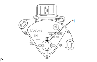
(c) Align the protrusions of the park/neutral position switch. Text in Illustration
|
|
|
(d) Hold the park/neutral position switch in position and tighten the 2 bolts. Torque: 5.4 N·m {55 kgf·cm, 48 in·lbf} NOTICE: After installing the park/neutral position switch, confirm that the 2 protrusions on the switch are aligned. |
|
(e) Install the transmission control shaft lever.
HINT:
See the steps from "Install Park/Neutral Position Switch Assembly" through "Install
Cool Air Intake Duct Seal" (See page ).
(f) After the adjustment, perform the switch operation check (See page
).
 Inspection
INSPECTION
PROCEDURE
1. INSPECT PARK/NEUTRAL POSITION SWITCH ASSEMBLY
(a) Measure the resistance according to the value(s) in the table below
when the shift lever is moved to each po ...
 Installation
INSTALLATION
PROCEDURE
1. INSTALL PARK/NEUTRAL POSITION SWITCH ASSEMBLY
(a) Move the shift lever to N.
(b) Align the protrusions of the park/neutral position switch.
Text in Illustra ...
Other materials about Toyota Venza:
Automatic High Beam
The Automatic High Beam uses an in-vehicle camera sensor to assess the brightness
of streetlights, the lights of oncoming and preceding vehicles, etc., and automatically
turns high beam on or off as necessary.
- Activating the Automatic High Beam sy ...
Removal
REMOVAL
CAUTION / NOTICE / HINT
HINT:
The front side fix window assembly can be reused. When installing the
window, if any of the clips on the front side fix window assembly are broken,
butyl tape can be used to support the glass until the a ...
Precaution
PRECAUTION
NOTICE:
When disconnecting the cable from the negative (-) battery terminal, initialize
the following system after the cable is reconnected.
System Name
See Procedure
Back Door Closer System
...

0.1404