Toyota Venza: Removal
REMOVAL
PROCEDURE
1. REMOVE FRONT SEAT HEADREST ASSEMBLY
2. REMOVE FRONT SEAT REAR OUTER TRACK COVER
.gif)
3. REMOVE FRONT SEAT REAR INNER TRACK COVER
4. REMOVE FRONT SEAT ASSEMBLY
5. REMOVE RECLINING POWER SEAT SWITCH KNOB
6. REMOVE SLIDE AND VERTICAL POWER SEAT SWITCH KNOB
7. REMOVE FRONT SEAT CUSHION SHIELD ASSEMBLY
8. REMOVE FRONT SEAT INNER BELT ASSEMBLY
9. REMOVE FRONT INNER SEAT CUSHION SHIELD
10. REMOVE POWER SEAT SWITCH
11. REMOVE SEPARATE TYPE FRONT SEAT CUSHION COVER WITH PAD
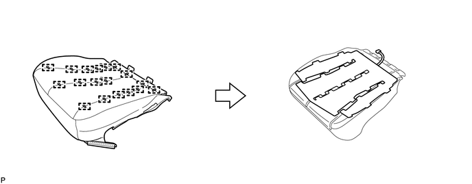
12. REMOVE SEPARATE TYPE FRONT SEAT CUSHION COVER
(a) Remove the 18 hog rings and the separate type front seat cushion cover.
|
(b) Cut off the 25 tack pins that fasten the seat heater, and then remove the separate type front seat cushion heater assembly from the separate type front seat cushion cover. |
|
.png)
 Components
COMPONENTS
ILLUSTRATION
ILLUSTRATION
ILLUSTRATION
...
 Inspection
INSPECTION
PROCEDURE
1. INSPECT FRONT SEAT CUSHION HEATER LH
(a) Check the seat cushion heater.
(1) Apply battery voltage and check the seat cushion heater.
OK:
...
Other materials about Toyota Venza:
Disassembly
DISASSEMBLY
PROCEDURE
1. REMOVE TRANSMISSION WIRE
2. REMOVE ATF TEMPERATURE SENSOR ASSEMBLY
(a) Remove the 4 bolts, ATF temperature sensor assembly and clamp from
the valve body assembly.
Text in Illustration
*1
...
Disassembly
DISASSEMBLY
PROCEDURE
1. REMOVE NO. 2 HEADLIGHT BULB (for Halogen Headlight)
(a) Turn the No. 2 headlight bulb in the direction indicated by the arrow
shown in the illustration, and remove it.
NOTICE:
Do not touch the bulb glass.
...
Reassembly
REASSEMBLY
PROCEDURE
1. INSTALL GENERATOR ROTOR ASSEMBLY
(a) Place the drive end frame on the clutch pulley.
(b) Install the generator rotor assembly to the drive end frame.
2. INSTALL GENERATOR CL ...

0.1391