Toyota Venza: Reassembly
REASSEMBLY
PROCEDURE
1. INSTALL GENERATOR ROTOR ASSEMBLY
(a) Place the drive end frame on the clutch pulley.
|
(b) Install the generator rotor assembly to the drive end frame. |
|
.png)
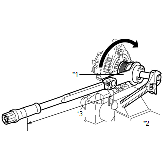
2. INSTALL GENERATOR CLUTCH PULLEY
(a) Temporarily install the clutch pulley onto the rotor shaft.
(b) Mount the generator drive end frame in a vise tightly.
|
(c) Confirm SST (A) and (B) shown in the illustration. Text in Illustration
SST: 09820-63021 |
|
.png)
|
(d) Place the rotor shaft end into SST (A). Text in Illustration
|
|
.png)
|
(e) Fit SST (B) to the clutch pulley. Text in Illustration
|
|
.png)
|
(f) Tighten the pulley by turning SST (B) in the direction shown in the illustration. Text in Illustration
Torque: without SST : 80 N·m {816 kgf·cm, 59 ft·lbf} with SST : 64 N·m {653 kgf·cm, 47 ft·lbf} NOTICE:
|
|
(g) Remove SST from the generator assembly.
(h) Check that the clutch pulley rotates smoothly.
(i) Install a new clutch pulley cap to the clutch pulley.
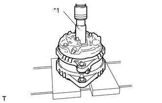
3. INSTALL GENERATOR COIL ASSEMBLY
|
(a) Place a new generator washer on the generator rotor. |
|
.png)
|
(b) Using a deep socket wrench (21 mm) and a press, slowly press in the generator coil assembly. Text in Illustration
|
|
|
(c) Install the 4 bolts. Torque: 5.9 N·m {60 kgf·cm, 52 in·lbf} |
|
.png)
4. INSTALL GENERATOR BRUSH HOLDER ASSEMBLY
|
(a) While pushing the 2 brushes into the generator brush holder assembly, insert a 1.0 mm (0.0394 in.) pin into the brush holder hole. Text in Illustration
|
|
.png)
|
(b) Install the brush holder assembly to the generator coil with the 2 screws. Torque: 1.8 N·m {18 kgf·cm, 16 in·lbf} |
|
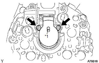
(c) Pull out the pin from the generator brush holder.
Text in Illustration|
*1 |
Pin |
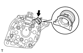
5. INSTALL TERMINAL INSULATOR
|
(a) Install the terminal insulator to the generator coil. NOTICE: Be sure to install the terminal insulator in the correct direction. |
|
6. INSTALL GENERATOR REAR END COVER
|
(a) Install the generator rear end cover to the generator coil with the 3 nuts. Torque: 4.6 N·m {47 kgf·cm, 41 in·lbf} |
|
.png)
 Installation
INSTALLATION
PROCEDURE
1. INSTALL GENERATOR ASSEMBLY
(a) Install the wire harness clamp with the bolt.
Torque:
8.4 N·m {86 kgf·cm, 74 in·lbf}
...
 Networking
...
Other materials about Toyota Venza:
ECM / PCM Processor (P0606)
MONITOR DESCRIPTION
The ECM continuously monitors its main and sub CPUs. This self-check ensures
that the ECM is functioning properly. If outputs from the CPUs are different and
deviate from the standard, the ECM illuminates the MIL and stores the DTC imm ...
Inspection
INSPECTION
PROCEDURE
1. INSPECT DRIVER SIDE LUMBAR SWITCH
(a) Measure the resistance between the terminals when the switch is operated.
Standard Resistance:
Tester Connection
Switch Condition
...
Removal
REMOVAL
PROCEDURE
1. PRECAUTION (w/ Navigation System)
NOTICE:
After turning the ignition switch off, waiting time may be required before disconnecting
the cable from the negative (-) battery terminal. Therefore, make sure to read the
disconnecting the ...

0.1548