Toyota Venza: Removal
REMOVAL
PROCEDURE
1. REMOVE AIR CONDITIONING UNIT ASSEMBLY
(See page .gif) )
)
2. REMOVE NO. 1 FINISH PANEL MOUNTING BRACKET
3. REMOVE NO. 2 FINISH PANEL MOUNTING BRACKET
4. REMOVE NO. 3 AIR DUCT SUB-ASSEMBLY
5. REMOVE NO. 2 AIR DUCT SUB-ASSEMBLY
6. REMOVE AIR CONDITIONING HARNESS ASSEMBLY
7. REMOVE COOLER EXPANSION VALVE
8. REMOVE BLOWER ASSEMBLY WITH COOLER EVAPORATOR SUB-ASSEMBLY
|
(a) Remove the 6 screws. |
|
.png)
|
(b) Disengage the guide and disconnect the wire harness. |
|
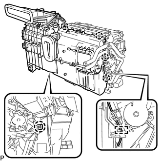
(c) Disengage the 5 claws and remove the blower assembly with cooler evaporator sub-assembly from the air conditioning radiator assembly.
9. REMOVE COOLER EVAPORATOR SUB-ASSEMBLY
10. REMOVE NO. 1 COOLER THERMISTOR
 Components
COMPONENTS
ILLUSTRATION
ILLUSTRATION
ILLUSTRATION
...
 Disassembly
DISASSEMBLY
PROCEDURE
1. REMOVE NO. 1 AIR DUCT SUB-ASSEMBLY
(a) Disengage the 4 claws and remove the No. 1 air duct sub-assembly.
2. REMOV ...
Other materials about Toyota Venza:
Navigation Receiver Assembly Power Source Circuit
DESCRIPTION
This is the power source circuit to operate the navigation receiver assembly.
WIRING DIAGRAM
CAUTION / NOTICE / HINT
NOTICE:
Inspect the fuses for circuits related to this system before performing the following
inspection procedure.
PROCE ...
Installation
INSTALLATION
PROCEDURE
1. INSTALL POWER DISTRIBUTION
(a) Connect the 3 connectors.
(b) Engage the 2 claws to temporarily install the power distribution
as shown in the illustration.
...
Problem Symptoms Table
PROBLEM SYMPTOMS TABLE
HINT:
Use the table below to help determine the cause of problem symptoms.
If multiple suspected areas are listed, the potential causes of the symptoms
are listed in order of probability in the "Suspected Area" ...

0.1154