Toyota Venza: Components
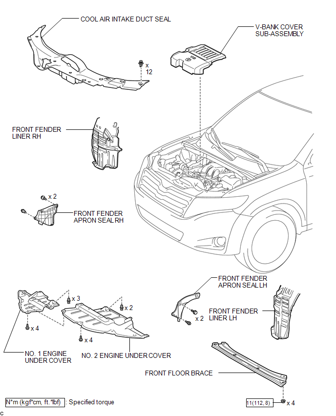
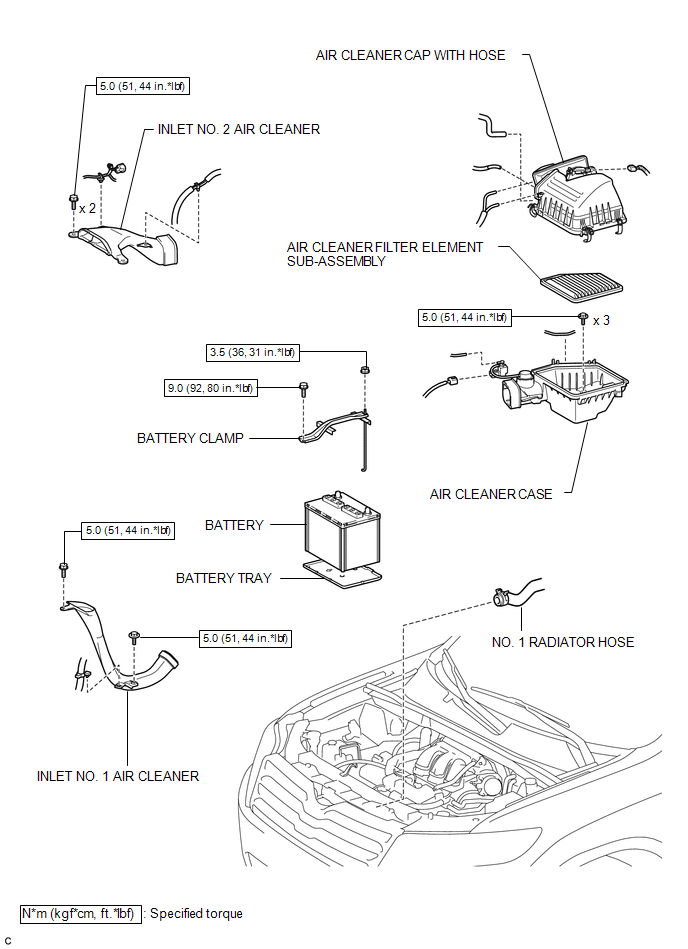
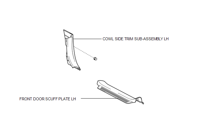
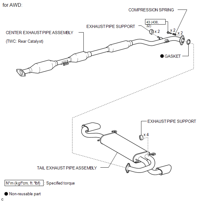
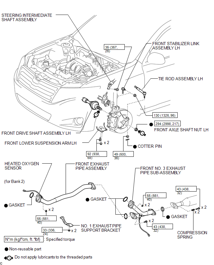
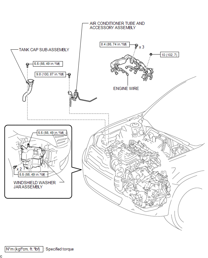
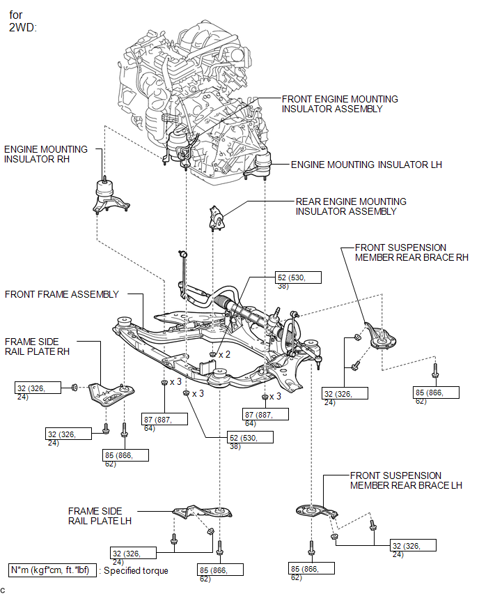
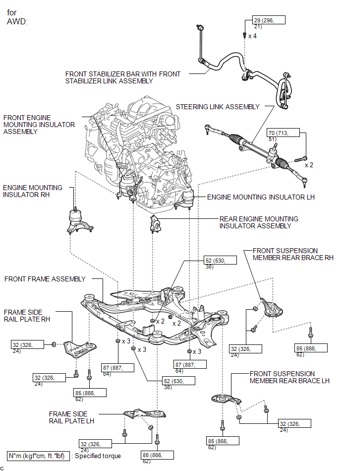
COMPONENTS
ILLUSTRATION
.png)
ILLUSTRATION
ILLUSTRATION
ILLUSTRATION
ILLUSTRATION
ILLUSTRATION
.png)
ILLUSTRATION
ILLUSTRATION
ILLUSTRATION
ILLUSTRATION
ILLUSTRATION
.png)
ILLUSTRATION
.png)

 Removal
REMOVAL
PROCEDURE
1. ALIGN FRONT WHEELS FACING STRAIGHT AHEAD
2. DISCONNECT CABLE FROM NEGATIVE BATTERY TERMINAL
NOTICE:
When disconnecting the cable, some systems need to be initialized after th ...
Other materials about Toyota Venza:
Installation
INSTALLATION
CAUTION / NOTICE / HINT
NOTICE:
If installing a new rear differential carrier assembly, remove the 2 differential
side seal caps before installing the rear drive shaft assembly.
PROCEDURE
1. INSTALL REAR DIFFERENTIAL DYNAMIC DAMPER
HINT:
...
Inspection
INSPECTION
CAUTION / NOTICE / HINT
NOTICE:
Ensure that fingers or articles of clothing do not get caught in moving parts
when performing this test.
PROCEDURE
1. INSPECT WINDSHIELD WIPER MOTOR ASSEMBLY
(a) Check the LO operation.
(1) Conne ...
Reassembly
REASSEMBLY
PROCEDURE
1. INSTALL FRONT OIL PUMP OIL SEAL
(a) Using SST and a hammer, install a new oil seal to the oil pump body.
SST: 09350-32014
09351-32140
Oil seal driven in depth:
-0.25 to 0.25 mm (-0.00984 to 0.00984 in.)
...

0.1267