Toyota Venza: Components
COMPONENTS
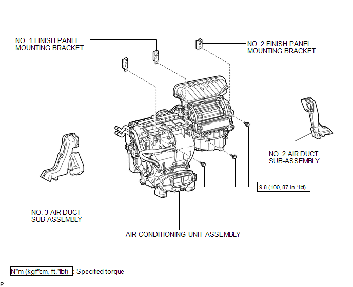
ILLUSTRATION
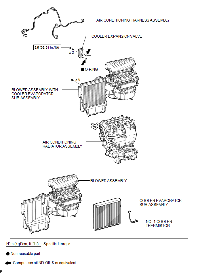
ILLUSTRATION
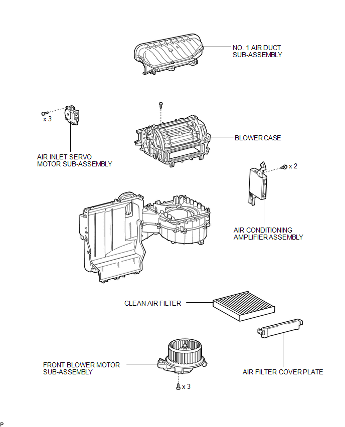
ILLUSTRATION
 Blower Unit
...
 Removal
REMOVAL
PROCEDURE
1. REMOVE AIR CONDITIONING UNIT ASSEMBLY
(See page )
2. REMOVE NO. 1 FINISH PANEL MOUNTING BRACKET
3. REMOVE NO. 2 FINISH PANEL MOUNTING BRACKET
4. REMOVE NO. 3 AIR DUCT ...
Other materials about Toyota Venza:
System Diagram
SYSTEM DIAGRAM
Input and Output Signal of Each ECU
Transmitting ECU (transmitter)
Receiving ECU
Signal
Communication Method
Power management Control ECU
Steering Lock ECU (Steering Lock ...
Brake Switch "A" / "B" Correlation (P0504)
DESCRIPTION
The stop light switch is a duplex system that transmits 2 signals: STP and ST1-.
These 2 signals are used by the ECM to monitor whether or not the brake system is
working properly. If signals which indicate the brake pedal is being depressed a ...
Removal
REMOVAL
PROCEDURE
1. REMOVE REAR SEAT HEADREST ASSEMBLY
2. REMOVE REAR SEAT INNER TRACK BRACKET COVER
3. REMOVE REAR SEAT OUTER TRACK BRACKET COVER
4. DISCONNECT REAR SEAT NO. 2 RECLINING CONTROL CABLE SUB-ASSEMBLY
5. REMOVE REAR SEAT ASSEMBL ...

0.1283