Toyota Venza: Disassembly
DISASSEMBLY
PROCEDURE
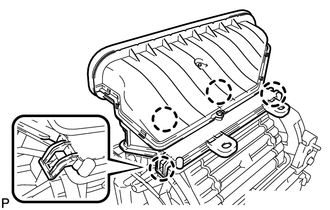
1. REMOVE NO. 1 AIR DUCT SUB-ASSEMBLY
|
(a) Disengage the 4 claws and remove the No. 1 air duct sub-assembly. |
|
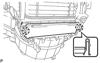
2. REMOVE AIR FILTER COVER PLATE
|
(a) Disengage the 2 claws and remove the air filter cover plate. |
|
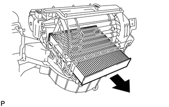
3. REMOVE CLEAN AIR FILTER
|
(a) Remove the clean air filter as shown in the illustration. |
|
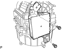
4. REMOVE AIR CONDITIONING AMPLIFIER ASSEMBLY
|
(a) Remove the 2 screws and air conditioning amplifier assembly. |
|
5. REMOVE AIR INLET SERVO MOTOR SUB-ASSEMBLY
|
(a) Remove the screw. |
|
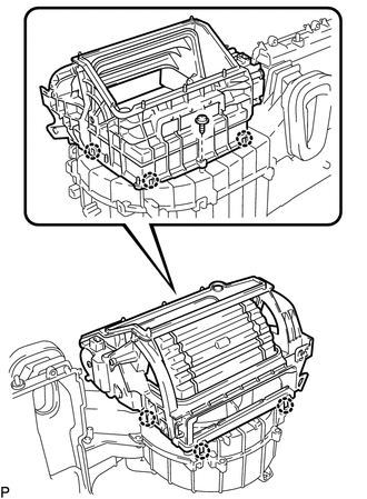
(b) Disengage the 6 claws and remove the blower case.
|
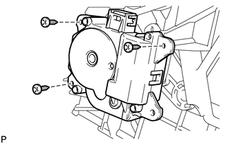
(c) Remove the 3 screws and air inlet servo motor sub-assembly. |
|
6. REMOVE FRONT BLOWER MOTOR SUB-ASSEMBLY
|
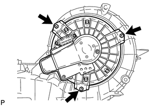
(a) Remove the 3 screws and front blower motor sub-assembly. |
|
 Removal
REMOVAL
PROCEDURE
1. REMOVE AIR CONDITIONING UNIT ASSEMBLY
(See page )
2. REMOVE NO. 1 FINISH PANEL MOUNTING BRACKET
3. REMOVE NO. 2 FINISH PANEL MOUNTING BRACKET
4. REMOVE NO. 3 AIR DUCT ...
 Reassembly
REASSEMBLY
PROCEDURE
1. INSTALL FRONT BLOWER MOTOR SUB-ASSEMBLY
(a) Install the front blower motor sub-assembly with the 3 screws.
2. INST ...
Other materials about Toyota Venza:
Components
COMPONENTS
ILLUSTRATION
ILLUSTRATION
ILLUSTRATION
ILLUSTRATION
ILLUSTRATION
ILLUSTRATION
ILLUSTRATION
...
Fuel Sender Open Detected (B1500)
DESCRIPTION
This DTC is output when the combination meter assembly detects a fuel sender
gauge malfunction via the direct line.
DTC No.
DTC Detection Condition
Trouble Area
B1500
When either of t ...
Removal
REMOVAL
PROCEDURE
1. REMOVE REAR BUMPER PLATE LH
(a) Using a screwdriver with the tip wrapped with protective tape, disengage
the 2 claws and remove the rear bumper plate LH.
Text in Illustration
*1
Pro ...

0.1727