Toyota Venza: Components
COMPONENTS
ILLUSTRATION
ILLUSTRATION
.png)
ILLUSTRATION
ILLUSTRATION

 Removal
REMOVAL
PROCEDURE
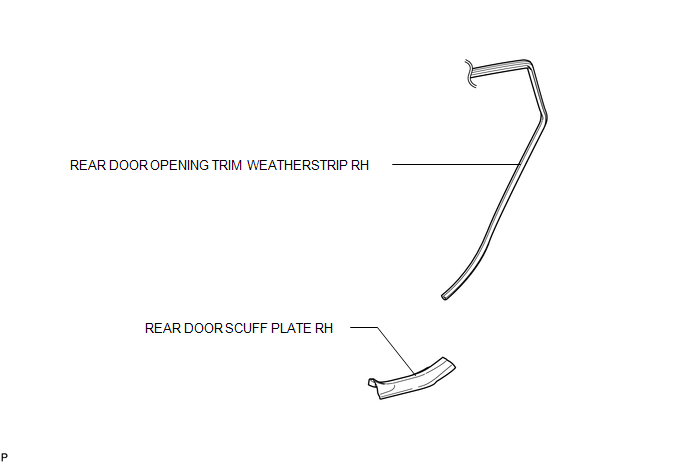
1. REMOVE REAR DOOR SCUFF PLATE RH
HINT:
Use the same procedure for the RH side and LH side (See page
).
2. DISCONNECT REAR DOOR OPENING TRIM WEATHERSTRIP RH
HINT:
Use the s ...
Other materials about Toyota Venza:
Child Restraint Seat Tether Anchor
Components
COMPONENTS
ILLUSTRATION
Installation
INSTALLATION
PROCEDURE
1. INSTALL CHILD RESTRAINT SEAT TETHER ANCHOR BRACKET
(a) Engage the guide.
(b) Install the child restraint seat teth ...
If a warning message is displayed
The multi-information display shows warnings of system malfunctions or incorrectly
performed operations. When a message is shown, perform corrections as indicated
in the message.
1. Master warning light
The master warning light comes on or flashes when ...
A/F Sensor Slow Response - Rich to Lean Bank 1 Sensor 1 (P014C,P014D,P015A,P015B)
DESCRIPTION
HINT:
Refer to DTC P2195 (See page ).
DTC No.
DTC Detection Condition
Trouble Area
P014C
The "Rich to Lean response rate deterioration level*" value is standard
or less ...

0.1479