Toyota Venza: Removal
REMOVAL
PROCEDURE
1. REMOVE BACK DOOR PANEL TRIM ASSEMBLY
.gif)
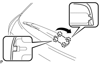
2. REMOVE REAR WIPER ARM HEAD CAP
|
(a) Disengage the 4 claws and remove the rear wiper arm head cap as shown in the illustration. |
|
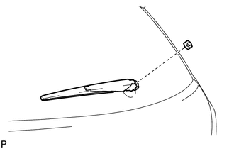
3. REMOVE REAR WIPER ARM AND BLADE ASSEMBLY
|
(a) Remove the nut and the rear wiper arm and blade assembly. |
|
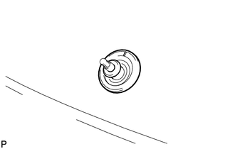
4. REMOVE REAR WIPER MOTOR GROMMET
|
(a) Remove the rear wiper motor grommet. |
|
5. REMOVE REAR WIPER MOTOR AND BRACKET ASSEMBLY
|
(a) Disconnect the connector. |
|
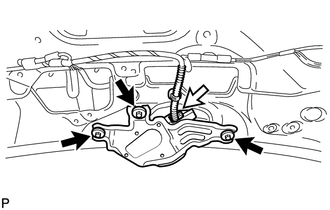
(b) Remove the 3 bolts and the rear wiper motor and bracket assembly.
 On-vehicle Inspection
ON-VEHICLE INSPECTION
PROCEDURE
1. INSPECT REAR WIPER MOTOR AND BRACKET ASSEMBLY
(a) Operate the rear wiper motor and bracket assembly.
(b ...
 Inspection
INSPECTION
PROCEDURE
1. INSPECT REAR WIPER MOTOR AND BRACKET ASSEMBLY
(a) Check the wiper low operation.
(1) Connect a battery positive (+) lead to terminal 4 (+B), and a negative (-)
lead to ...
Other materials about Toyota Venza:
Short in Sensor with Motor Power Supply Circuit (B2658)
DESCRIPTION
This DTC is stored if sensor voltage does not reach the designated voltage while
the slide motor is operating.
DTC Code
DTC Detection Condition
Trouble Area
B2658
Malfunction in suppl ...
Cellular Phone Inspection
PROCEDURE
1.
CHECK USAGE CONDITION
(a) Check that the vehicle and cellular phone meet the following conditions:
NOTICE:
If changing cellular phone settings, updating software, etc. is necessary, make
sure to obtain the per ...
Driver Side Door ECU Communication Stop (B2321)
DESCRIPTION
This DTC is stored when LIN communication between the power window regulator
motor assembly (for driver side) and main body ECU (driver side junction block assembly)
stops for more than 10 seconds.
DTC No.
DTC Detection ...

0.1634