Toyota Venza: Installation
INSTALLATION
CAUTION / NOTICE / HINT
HINT:
- Use the same procedure for the RH side and LH side.
- The procedure listed below is for the LH side.
PROCEDURE
1. INSTALL CURTAIN SHIELD AIRBAG ASSEMBLY
(a) Check that the ignition switch is off.
(b) Check that the cable is disconnected from the negative (-) battery terminal.
CAUTION:
Wait at least 90 seconds after disconnecting the cable from the negative (-) battery terminal to disable the SRS system.
(c) Engage the 13 hooks to temporarily install the curtain shield airbag assembly.
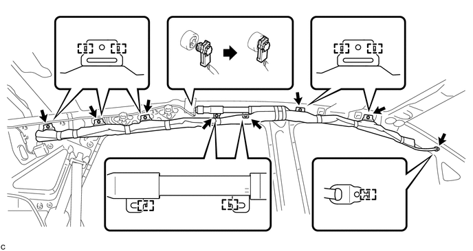
NOTICE:
Do not twist the curtain shield airbag assembly when installing it.
(d) Install 8 new bolts.
Torque:
11 N·m {112 kgf·cm, 8 ft·lbf}
(e) Connect the curtain shield airbag connector.
NOTICE:
When connecting the airbag connector, take care not to damage the airbag wire harness.
2. INSTALL ROOF HEADLINING ASSEMBLY
HINT:
Refer to the procedure from Install Roof Headlining Assembly (See page
.gif) ).
).
3. CONNECT CABLE TO NEGATIVE BATTERY TERMINAL
NOTICE:
When disconnecting the cable, some systems need to be initialized after the cable
is reconnected (See page ).
4. PERFORM DIAGNOSTIC SYSTEM CHECK
(a) Perform a diagnostic system check (See page
).
5. INSPECT SRS WARNING LIGHT
(a) Inspect the SRS warning light (See page
).
 Removal
REMOVAL
CAUTION / NOTICE / HINT
HINT:
Use the same procedure for the RH side and LH side.
The procedure listed below is for the LH side.
PROCEDURE
1. PRECAUTION
CAUTION:
Be su ...
 Disposal
DISPOSAL
CAUTION / NOTICE / HINT
CAUTION:
Before performing pre-disposal deployment of any SRS component, review and closely
follow all applicable environmental and hazardous material regulations ...
Other materials about Toyota Venza:
Driving assist systems
To help enhance driving safety and performance, the following systems operate
automatically in response to various driving situations.
Be aware, however, that these systems are supplementary and should not be relied
upon too heavily when operating the veh ...
Precaution
PRECAUTION
1. WHEN DISCONNECTING CABLE FROM NEGATIVE BATTERY TERMINAL
NOTICE:
When disconnecting the cable from the negative (-) battery terminal, initialize
the following systems after the cable is reconnected.
System Name
See Proc ...
Problem Symptoms Table
PROBLEM SYMPTOMS TABLE
HINT:
Use the table below to help determine the cause of problem symptoms.
If multiple suspected areas are listed, the potential causes of the symptoms
are listed in order of probability in the "Suspected Area" ...

0.1418