Toyota Venza: Removal
REMOVAL
PROCEDURE
1. REMOVE BACK DOOR PANEL TRIM ASSEMBLY
.gif)
2. REMOVE REAR WIPER ARM HEAD CAP
3. REMOVE REAR WIPER ARM AND BLADE ASSEMBLY
4. REMOVE REAR WIPER MOTOR GROMMET
5. REMOVE REAR WIPER MOTOR AND BRACKET ASSEMBLY
6. REMOVE REAR LIGHT ASSEMBLY LH
7. REMOVE REAR LIGHT ASSEMBLY RH
HINT:
Use the same procedure for the RH side and LH side.
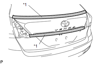
8. REMOVE BACK DOOR OUTSIDE GARNISH SUB-ASSEMBLY
|
(a) Put protective tape around the back door outside garnish sub-assembly. Text in Illustration
|
|
(b) Disconnect each connector.
|
(c) Remove the 5 nuts. |
|
.png)
|
(d) Disengage the 16 clips and remove the back door outside garnish sub-assembly. |
|
.png)
(e) Remove the 16 clips (back door moulding clip) from the back door outside garnish sub-assembly.
(f) Remove the 5 gaskets and 5 stud bolts from the back door outside garnish sub-assembly.
9. REMOVE NO. 1 BACK DOOR EMBLEM
10. REMOVE NO. 2 BACK DOOR NAME PLATE
11. REMOVE BACK DOOR OPENER SWITCH ASSEMBLY
12. REMOVE TELEVISION CAMERA ASSEMBLY (w/ Rear View Monitor System)
 Installation
INSTALLATION
PROCEDURE
1. INSTALL TELEVISION CAMERA ASSEMBLY (w/ Rear View Monitor System)
2. INSTALL BACK DOOR OPENER SWITCH ASSEMBLY
3. INSTALL NO. 1 BACK DOOR EMBLEM
4. INSTALL NO. 2 ...

Other materials about Toyota Venza:
Unmatched Encryption Code (B2794)
DESCRIPTION
This DTC is stored when a key with an incomplete key code is inserted into the
ignition key cylinder.
DTC No.
DTC Detection Condition
Trouble Area
B2794
Key with incomplete key code i ...
Inspection
INSPECTION
PROCEDURE
1. INSPECT BRAKE VACUUM CHECK VALVE ASSEMBLY
(a) Check that there is ventilation from the booster to the engine, and
no ventilation from the engine to the booster.
If the results are not as specified, replace the brake ...
Installation
INSTALLATION
CAUTION / NOTICE / HINT
NOTICE:
If installing a new rear differential carrier assembly, remove the 2 differential
side seal caps before installing the rear drive shaft assembly.
PROCEDURE
1. INSTALL REAR DIFFERENTIAL DYNAMIC DAMPER
HINT:
...

0.1132