Toyota Venza: Installation
INSTALLATION
CAUTION / NOTICE / HINT
NOTICE:
If installing a new rear differential carrier assembly, remove the 2 differential side seal caps before installing the rear drive shaft assembly.
PROCEDURE
1. INSTALL REAR DIFFERENTIAL DYNAMIC DAMPER
HINT:
This step should be performed only when the rear differential dynamic damper is replaced.
|
(a) Install the rear differential dynamic damper with the bolt. Torque: 27 N·m {270 kgf·cm, 20 ft·lbf} |
|
.png)
2. TEMPORARILY TIGHTEN REAR NO. 1 DIFFERENTIAL SUPPORT
|
(a) Temporarily install the rear No. 1 differential support to the differential carrier assembly with 2 new bolts and 2 new nuts. NOTICE:
HINT: The nuts have tabs to prevent them from rotating. |
|
3. INSTALL DIFFERENTIAL SUPPORT
|
(a) Install the differential support to the differential carrier assembly with 3 new bolts. Torque: 167 N·m {1700 kgf·cm, 123 ft·lbf} |
|
.png)
4. TEMPORARILY TIGHTEN REAR DIFFERENTIAL CARRIER ASSEMBLY WITH DIFFERENTIAL SUPPORT
|
(a) Temporarily install the rear differential carrier assembly with differential support to the rear side of the rear suspension member assembly with the 3 rear mounting bolts. |
|
.png)
|
(b) Temporarily install the rear differential carrier assembly with differential support to the front side of the rear suspension member assembly with the 2 bolts and 2 nuts. HINT: The nuts have tabs to prevent them from rotating. |
|
.png)
5. FULLY TIGHTEN REAR DIFFERENTIAL CARRIER ASSEMBLY WITH DIFFERENTIAL SUPPORT
NOTICE:
Do not tighten the bolts with the inner cylinder or rear differential mount cushion tilted.
|
(a) Install the rear differential carrier assembly with differential support to the rear side of the rear suspension member assembly with the 3 rear mounting bolts. Torque: 95 N·m {970 kgf·cm, 70 ft·lbf} |
|
|
(b) Install the rear differential carrier assembly with differential support to the front side of the rear suspension member assembly with the 2 bolts and 2 nuts. Torque: 114 N·m {1162 kgf·cm, 84 ft·lbf} HINT: The nuts have tabs to prevent them from rotating. |
|
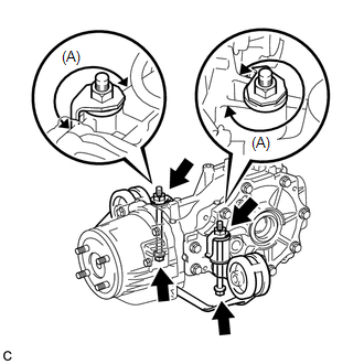
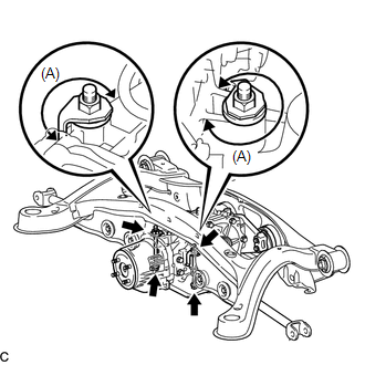
6. FULLY TIGHTEN REAR NO. 1 DIFFERENTIAL SUPPORT
|
(a) Install the rear No. 1 differential support to the rear differential carrier assembly with the 2 new bolts and 2 new nuts. Torque: 86 N·m {877 kgf·cm, 63 ft·lbf} NOTICE: Make sure that each nut is installed to position (A) shown in the illustration. HINT: The nuts have tabs to prevent them from rotating. |
|
7. INSTALL REAR SUSPENSION MEMBER
.gif)
8. INSTALL FRAME WIRE
9. INSTALL NO. 3 FLOOR WIRE (w/ HID Headlight System)
10. INSTALL REAR DRIVE SHAFT SNAP RING LH
11. INSTALL REAR DRIVE SHAFT ASSEMBLY LH
12. INSTALL REAR DRIVE SHAFT SNAP RING RH
13. INSTALL REAR DRIVE SHAFT ASSEMBLY RH
14. CONNECT REAR NO. 1 SUSPENSION ARM ASSEMBLY LH
15. CONNECT REAR NO. 1 SUSPENSION ARM ASSEMBLY RH
16. TEMPORARILY TIGHTEN REAR NO. 2 SUSPENSION ARM ASSEMBLY LH
17. TEMPORARILY TIGHTEN REAR NO. 2 SUSPENSION ARM ASSEMBLY RH
18. INSTALL REAR STRUT ROD ASSEMBLY LH
19. INSTALL REAR STRUT ROD ASSEMBLY RH
20. INSTALL REAR HEIGHT CONTROL SENSOR SUB-ASSEMBLY (w/ HID Headlight System)
21. INSTALL NO. 3 PARKING BRAKE CABLE ASSEMBLY
22. INSTALL NO. 2 PARKING BRAKE CABLE ASSEMBLY
23. INSTALL REAR AXLE SHAFT NUT LH
24. INSTALL REAR AXLE SHAFT NUT RH
25. INSTALL REAR SPEED SENSOR LH
26. INSTALL REAR SPEED SENSOR RH
27. TEMPORARILY TIGHTEN PROPELLER WITH CENTER BEARING SHAFT ASSEMBLY
28. FULLY TIGHTEN PROPELLER WITH CENTER BEARING SHAFT ASSEMBLY
29. INSTALL NO. 1 FLOOR UNDER COVER
30. INSPECT AND ADJUST TRANSFER OIL
(a) Inspect and adjust transfer oil (See page
).
31. INSTALL CENTER EXHAUST PIPE ASSEMBLY
(a) Install the center exhaust pipe assembly.
HINT:
Refer to the instructions for Installation of the exhaust pipe (See page
for 2GR-FE,
for 1AR-FE).
32. ADD DIFFERENTIAL OIL
(a) When reusing the rear differential carrier assembly:
|
(1) Using a 10 mm hexagon wrench, install a new gasket and the rear differential drain plug. Torque: 39 N·m {398 kgf·cm, 29 ft·lbf} |
|
.png)
(2) Add differential oil (See page ).
(b) When using a new rear differential carrier assembly:
|
(1) Using a 10 mm hexagon wrench, remove the rear differential carrier cover plug and gasket. |
|
.png)
(2) Add differential oil (See page ).
33. INSPECT DIFFERENTIAL OIL
34. INSTALL REAR DIFFERENTIAL CARRIER COVER PLUG
35. INSPECT FOR DIFFERENTIAL OIL LEAK
36. INSPECT FOR EXHAUST GAS LEAK
37. INSTALL REAR WHEELS
Torque:
103 N·m {1050 kgf·cm, 76 ft·lbf}
38. STABILIZE SUSPENSION
39. FULLY TIGHTEN REAR NO. 2 SUSPENSION ARM ASSEMBLY LH
40. FULLY TIGHTEN REAR NO. 2 SUSPENSION ARM ASSEMBLY RH
41. INSPECT AND ADJUST REAR WHEEL ALIGNMENT
(a) Inspect and adjust the rear wheel alignment (See page
).
42. CHECK FOR SPEED SENSOR SIGNAL
(a) Check for the speed sensor signal (See page
).
43. HEIGHT CONTROL SENSOR SIGNAL INITIALIZATION (w/ HID Headlight System)
(a) Initialize the height control sensor signal (See page
).
44. INSPECT AND ADJUST HEADLIGHT AIMING (w/ HID Headlight System)
(a) Inspect and adjust the headlight aiming (See page
).
 Reassembly
REASSEMBLY
CAUTION / NOTICE / HINT
HINT:
Use an overhaul stand as necessary.
PROCEDURE
1. INSTALL DIFFERENTIAL RING GEAR
(a) Clean the contact surfaces of the rear differential case sub-assembly ...

Other materials about Toyota Venza:
Power Management Control ECU Communication Stop Mode
DESCRIPTION
Detection Item
Symptom
Trouble Area
Power Management Control ECU Communication Stop Mode
"Electric Power Control" is not displayed on the CAN Bus Check
screen ...
Fog light switch
The fog lights improve visibility in difficult driving conditions, such as
in rain or fog. The fog lights can be used when the headlights are on low beam.
Type A
1. Off
2. On
Type B
1. Off
2. On
Wiper intervals can be adjusted for intermittent ...
Installation
INSTALLATION
PROCEDURE
1. INSTALL NO. 1 COOLER THERMISTOR
2. INSTALL COOLER EVAPORATOR SUB-ASSEMBLY
3. INSTALL BLOWER ASSEMBLY WITH COOLER EVAPORATOR SUB-ASSEMBLY
(a) Engage the 5 claws.
(b) Engage the guide and connect the wire harness.
(c) Insta ...

0.1493