Toyota Venza: Removal
REMOVAL
CAUTION / NOTICE / HINT
HINT:
- Use the same procedure for the LH side and RH side.
- The following procedure listed below is for the LH side.
PROCEDURE
1. REMOVE FRONT WHEEL
2. REMOVE FRONT WIPER ARM HEAD CAP
.gif)
3. REMOVE FRONT WIPER ARM AND BLADE ASSEMBLY LH
4. REMOVE FRONT WIPER ARM AND BLADE ASSEMBLY RH
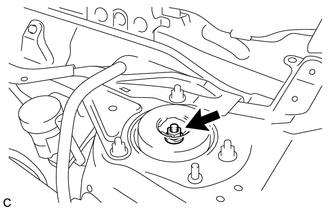
5. LOOSEN FRONT SUSPENSION SUPPORT NUT
|
(a) Loosen the front suspension support nut of the front shock absorber. NOTICE:
|
|
6. REMOVE FRONT FENDER TO COWL SIDE SEAL LH
7. REMOVE FRONT FENDER TO COWL SIDE SEAL RH
8. REMOVE COWL TOP VENTILATOR LOUVER SUB-ASSEMBLY
9. REMOVE WINDSHIELD WIPER MOTOR AND LINK ASSEMBLY
10. REMOVE OUTER COWL TOP PANEL
|
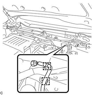
(a) Disengage the 2 clamps and separate the wiper wire harness from the outer cowl top panel sub-assembly. |
|
|
(b) Disengage the 2 clamps and connector, and separate the wire harness from the outer cowl top panel sub-assembly (w/ Windshield Deicer). |
|

|
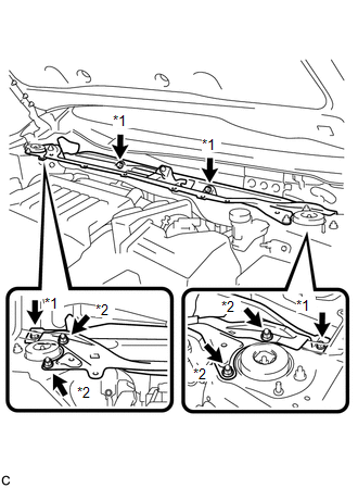
(c) Remove the 4 bolts, 4 nuts and outer cowl top panel sub-assembly. Text in Illustration
|
|
11. SEPARATE FRONT SPEED SENSOR
|
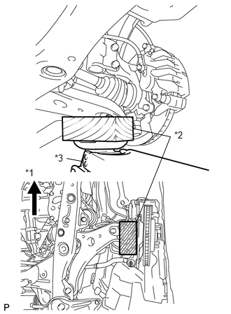
(a) Remove the bolt and clamp, and separate the front speed sensor and front flexible hose. |
|
.png)
12. SEPARATE FRONT STABILIZER LINK ASSEMBLY
|
(a) Remove the nut and separate the front stabilizer link assembly from the front shock absorber. HINT: If the ball joint turns together with the nut, use a hexagon wrench (6 mm) to hold the stud bolt. |
|
13. REMOVE FRONT SHOCK ABSORBER WITH COIL SPRING
|
(a) Support the front axle using a jack and wooden block. Text in Illustration
|
|
|
(b) Remove the 2 bolts and 2 nuts, and separate the front shock absorber with coil spring (lower side) from the steering knuckle. NOTICE: When removing the nuts, keep the bolts from rotating. |
|
.png)
|
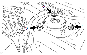
(c) Remove the nut and 2 spacers on the front shock absorber with coil spring (upper side). Text in Illustration
NOTICE: Make sure that the front speed sensor is completely separated from the front shock absorber with coil spring. |
|
14. SECURE FRONT SHOCK ABSORBER WITH COIL SPRING
|
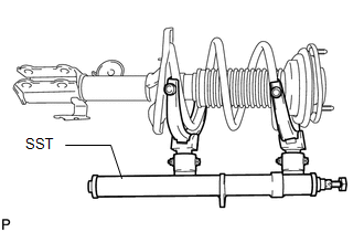
(a) Install SST to the front coil spring with the hooks spread as far apart as possible from each other. SST: 09727-00050 SST: 09727-30021 09727-00010 09727-00031 NOTICE: Make sure that the claws on the hooks are securely engaged to the spring. |
|
|
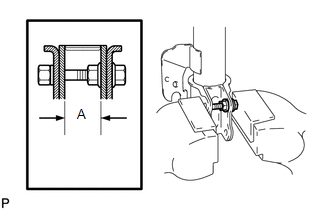
(b) Install the bolt and nut to the front shock absorber as shown in the illustration and secure the front shock absorber in a vise using aluminum plates. A: 28 mm (1.10 in.) |
|
15. REMOVE FRONT SUSPENSION SUPPORT NUT
|
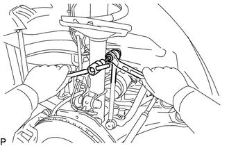
(a) Using SST, compress the front coil spring. SST: 09727-00050 SST: 09727-30021 09727-00010 09727-00031 NOTICE: Do not use an impact wrench. It will damage SST. HINT: If the front coil spring is compressed at an angle, using 2 SST will make the work easier. |
|
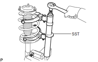
(b) Check that the front coil spring is fully compressed.
|
(c) Remove the front suspension support nut. |
|
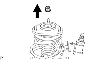
16. REMOVE FRONT SUSPENSION SUPPORT SUB-ASSEMBLY
17. REMOVE FRONT SUSPENSION SUPPORT BEARING
18. REMOVE FRONT COIL SPRING UPPER SEAT
19. REMOVE FRONT COIL SPRING UPPER INSULATOR
20. REMOVE FRONT COIL SPRING
21. REMOVE FRONT SPRING BUMPER
22. REMOVE FRONT COIL SPRING LOWER INSULATOR
 Components
COMPONENTS
ILLUSTRATION
ILLUSTRATION
ILLUSTRATION
...
 Inspection
INSPECTION
PROCEDURE
1. INSPECT FRONT SHOCK ABSORBER ASSEMBLY
(a) Compress and extend the shock absorber rod 4 or more times.
Standard:
There is no abnormal resistance or sound an ...
Other materials about Toyota Venza:
Disassembly
DISASSEMBLY
PROCEDURE
1. REMOVE TRANSMISSION WIRE
2. REMOVE ATF TEMPERATURE SENSOR ASSEMBLY
(a) Remove the 4 bolts, ATF temperature sensor assembly and clamp from
the valve body assembly.
Text in Illustration
*1
...
System Description
SYSTEM DESCRIPTION
1. AUTOMATIC LIGHT CONTROL SYSTEM
When the light control switch is in the AUTO position, the automatic light control
system detects ambient light levels and controls the low beam headlights, parking
lights, taillights, marker lights an ...
Diagnosis System
DIAGNOSIS SYSTEM
1. DESCRIPTION
(a) Data of the system can be read from the Data Link Connector 3 (DLC3) of the
vehicle. Therefore, when the system seems to be malfunctioning, use the Techstream
to check for a malfunction and repair it.
2. CHECK DLC3
( ...

0.1637