Toyota Venza: Disassembly
DISASSEMBLY
PROCEDURE
1. REMOVE STEERING RACK BOOT CLIP (for LH Side)
(a) Using pliers, remove the steering rack boot clip.
2. REMOVE STEERING RACK BOOT CLIP (for RH Side)
HINT:
Perform the same procedure as for the LH side.
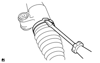
3. REMOVE NO. 2 STEERING RACK BOOT CLAMP
|
(a) Using a screwdriver, remove the No. 2 steering rack boot clamp. NOTICE: Be careful not to damage the steering rack boot. |
|
4. REMOVE NO. 1 STEERING RACK BOOT CLAMP
HINT:
Perform the same procedure as for the No. 2 steering rack boot clamp.
5. REMOVE NO. 2 STEERING RACK BOOT
6. REMOVE NO. 1 STEERING RACK BOOT
 Removal
REMOVAL
CAUTION / NOTICE / HINT
NOTICE:
When disconnecting the steering intermediate shaft assembly and pinion shaft
of steering gear assembly, be sure to place matchmarks before servicing.
PROC ...
 Inspection
INSPECTION
PROCEDURE
1. INSPECT TIE ROD ASSEMBLY LH
(a) Secure the tie rod assembly LH in a vise.
(b) Install the nut to the stud bolt.
( ...
Other materials about Toyota Venza:
Under Hood
General Maintenance
GENERAL MAINTENANCE
PROCEDURE
1. GENERAL NOTES
Maintenance requirements vary depending on the country.
Check the maintenance schedule in the owner's manual supplement.
Following the maintenance schedule is mandat ...
Reassembly
REASSEMBLY
PROCEDURE
1. INSTALL TRANSFER DRIVEN PINION REAR BEARING
(a) Using SST and a press, press the transfer driven pinion rear bearing
(outer race) to the case.
SST: 09950-60010
09951-00620
SST: 09950-70010
09951-07150
NO ...
Adjustment
ADJUSTMENT
CAUTION / NOTICE / HINT
CAUTION:
Before adjusting the door positions of vehicles equipped with side and curtain
shield airbags, be sure to disconnect the battery. After adjustment, check that
the SRS warning light is operating normally and ...

0.1269