Toyota Venza: Seat Belt Buckle Switch LH Circuit Malfunction (B1656/38)
DESCRIPTION
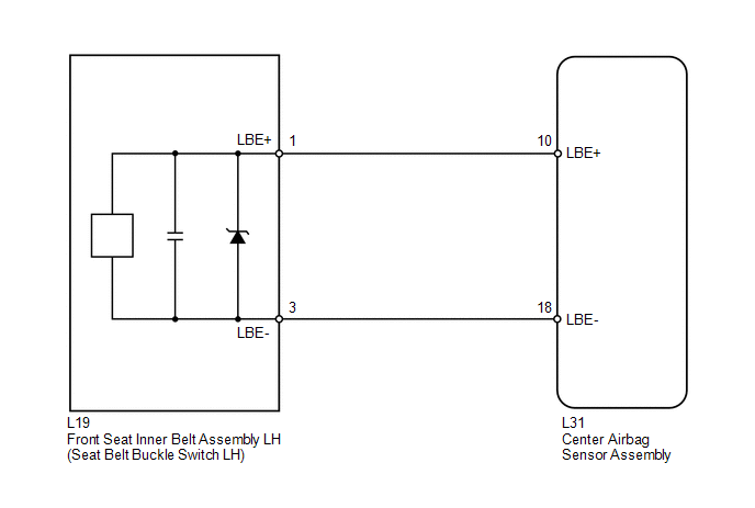
The seat belt buckle switch LH circuit consists of the center airbag sensor assembly and front seat inner belt assembly LH.
DTC B1656/38 is stored when a malfunction is detected in the seat belt buckle switch LH circuit.
|
DTC No. |
DTC Detection Condition |
Trouble Area |
|---|---|---|
|
B1656/38 |
|
|
WIRING DIAGRAM
PROCEDURE
|
1. |
CHECK CONNECTORS |
(a) Turn the ignition switch off.
(b) Disconnect the cable from the negative (-) battery terminal, and wait for at least 90 seconds.
(c) Check that the connectors are properly connected to the center airbag sensor assembly and front seat inner belt assembly LH.
OK:
The connectors are properly connected.
HINT:
If the connectors are not connected securely, reconnect the connectors and proceed to the next inspection.
(d) Disconnect the connectors from the center airbag sensor assembly and front seat inner belt assembly LH.
(e) Check that the terminals of connectors are not damaged.
OK:
The terminals are not deformed or damaged.
| NG | .gif) |
REPLACE FLOOR WIRE |
|
.gif)
|
2. |
CHECK FLOOR WIRE (OPEN) |
(a) Using SST, connect terminals 10 (LBE+) and 18 (LBE-) of connector B.
NOTICE:
Do not forcibly insert SST into the terminals of the connector when connecting the wire.
SST: 09843-18040
(b) Measure the resistance according to the value(s) in the table below.
Standard Resistance:
|
Tester Connection |
Condition |
Specified Condition |
|---|---|---|
|
L19-1 (LBE+) - L19-3 (LBE-) |
Always |
Below 1 Ω |
|
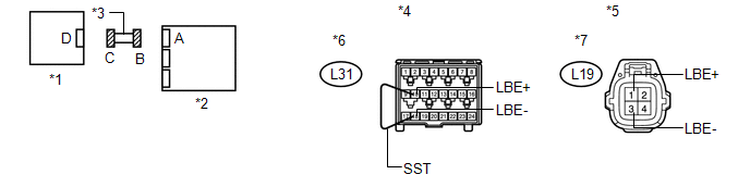
*1 |
Front Seat Inner Belt Assembly LH |
*2 |
Center Airbag Sensor Assembly |
|
*3 |
Floor Wire |
*4 |
Front view of wire harness connector (to Center Airbag Sensor Assembly) |
|
*5 |
Front view of wire harness connector (to Front Seat Inner Belt Assembly LH) |
*6 |
Connector B |
|
*7 |
Connector C |
- |
- |
| NG | |
REPLACE FLOOR WIRE |
|
|
3. |
CHECK FLOOR WIRE (SHORT) |
|
(a) Disconnect SST from connector B. |
|
(b) Measure the resistance according to the value(s) in the table below.
Standard Resistance:
|
Tester Connection |
Condition |
Specified Condition |
|---|---|---|
|
L19-1 (LBE+) - L19-3 (LBE-) |
Always |
1 MΩ or higher |
|
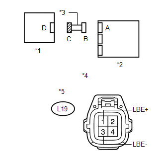
*1 |
Front Seat Inner Belt Assembly LH |
|
*2 |
Center Airbag Sensor Assembly |
|
*3 |
Floor Wire |
|
*4 |
Front view of wire harness connector (to Front Seat Inner Belt Assembly LH) |
|
*5 |
Connector C |
| NG | |
REPLACE FLOOR WIRE |
|
|
4. |
CHECK FLOOR WIRE (SHORT TO B+) |
|
(a) Connect the cable to the negative (-) battery terminal. |
|
(b) Turn the ignition switch to ON.
(c) Measure the voltage according to the value(s) in the table below.
Standard Voltage:
|
Tester Connection |
Switch Condition |
Specified Condition |
|---|---|---|
|
L19-1 (LBE+) - Body ground |
Ignition switch ON |
Below 1 V |
|
L19-3 (LBE-) - Body ground |
Ignition switch ON |
Below 1 V |
|
*1 |
Front Seat Inner Belt Assembly LH |
|
*2 |
Center Airbag Sensor Assembly |
|
*3 |
Floor Wire |
|
*4 |
Front view of wire harness connector (to Front Seat Inner Belt Assembly LH) |
|
*5 |
Connector C |
| NG | |
REPLACE FLOOR WIRE |
|
|
5. |
CHECK FLOOR WIRE (SHORT TO GROUND) |
|
(a) Turn the ignition switch off. |
|
(b) Disconnect the cable from the negative (-) battery terminal, and wait for at least 90 seconds.
(c) Measure the resistance according to the value(s) in the table below.
Standard Resistance:
|
Tester Connection |
Condition |
Specified Condition |
|---|---|---|
|
L19-1 (LBE+) - Body ground |
Always |
1 MΩ or higher |
|
L19-3 (LBE-) - Body ground |
Always |
1 MΩ or higher |
|
*1 |
Front Seat Inner Belt Assembly LH |
|
*2 |
Center Airbag Sensor Assembly |
|
*3 |
Floor Wire |
|
*4 |
Front view of wire harness connector (to Front Seat Inner Belt Assembly LH) |
|
*5 |
Connector C |
| NG | |
REPLACE FLOOR WIRE |
|
|
6. |
CHECK FRONT SEAT INNER BELT ASSEMBLY LH |
|
(a) Connect the connectors to the center airbag sensor assembly and front seat inner belt assembly LH. |
|
(b) Connect the cable to the negative (-) battery terminal.
(c) Turn the ignition switch to ON, and wait for at least 60 seconds.
(d) Clear the DTCs stored in memory (See page
.gif) ).
).
(e) Turn the ignition switch off.
(f) Turn the ignition switch to ON, and wait for at least 60 seconds.
(g) Check for DTCs (See page ).
OK:
DTC B1656/38 is not output.
Text in Illustration|
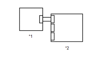
*1 |
Front Seat Inner Belt Assembly LH |
|
*2 |
Center Airbag Sensor Assembly |
HINT:
Codes other than DTC B1656/38 may be output at this time, but they are not related to this check.
| OK | |
USE SIMULATION METHOD TO CHECK |
|
|
7. |
REPLACE FRONT SEAT INNER BELT ASSEMBLY LH |
(a) Turn the ignition switch off.
(b) Disconnect the cable from the negative (-) battery terminal, and wait for at least 90 seconds.
(c) Replace the front seat inner belt assembly LH with a known good part (See
page ).
HINT:
Perform the following inspection using known good parts from another vehicle if possible.
|
|
8. |
CHECK CENTER AIRBAG SENSOR ASSEMBLY |
|
(a) Connect the cable to the negative (-) battery terminal. |
|
(b) Turn the ignition switch to ON, and wait for at least 60 seconds.
(c) Clear the DTCs stored in memory (See page
).
(d) Turn the ignition switch off.
(e) Turn the ignition switch to ON, and wait for at least 60 seconds.
(f) Check for DTCs (See page ).
OK:
DTC B1656/38 is not output.
Text in Illustration|
*1 |
Front Seat Inner Belt Assembly LH |
|
*2 |
Center Airbag Sensor Assembly |
HINT:
Codes other than DTC B1656/38 may be output at this time, but they are not related to this check.
| OK | |
END |
| NG | |
REPLACE CENTER AIRBAG SENSOR ASSEMBLY |
 Short in Front Pretensioner Squib LH Circuit (B1905/74-B1908/74)
DESCRIPTION
The front pretensioner squib LH circuit consists of the center airbag sensor
assembly and front seat outer belt assembly LH.
The center airbag sensor assembly uses this circuit to depl ...
 Seat Position Airbag Sensor Circuit Malfunction (B1653/35)
DESCRIPTION
The seat position airbag sensor circuit consists of the center airbag sensor
assembly and seat position airbag sensor.
DTC B1653/35 is stored when a malfunction is detected in the seat ...
Other materials about Toyota Venza:
Removal
REMOVAL
PROCEDURE
1. REMOVE INSTRUMENT PANEL SAFETY PAD ASSEMBLY
(See page )
2. REMOVE NO. 1 ANTENNA CORD SUB-ASSEMBLY
(a) Disengage the 7 clamps and remove the No. 1 antenna cord sub-assembly.
3. REMOVE ROOF HEADLINING ASSEMBLY
(See page )
4. REMO ...
Rear Power Window RH Auto Up / Down Function does not Operate with Rear Power
Window Switch RH
DESCRIPTION
If the manual up/down function can be performed but the auto up/down function
cannot, the fail-safe mode may be functioning.
If the power window initialization (See page
) has not been performed, the auto up/down function
will not operate.
...
Power outlets
The power outlets can be used for 12V accessories that run on less than 10A.
►Console box
►Front passenger’s side instrument panel
►Luggage compartment
- The power outlets can be used when
►Vehicles with smart key sys ...

0.1314