Toyota Venza: Refrigerant Line
Components
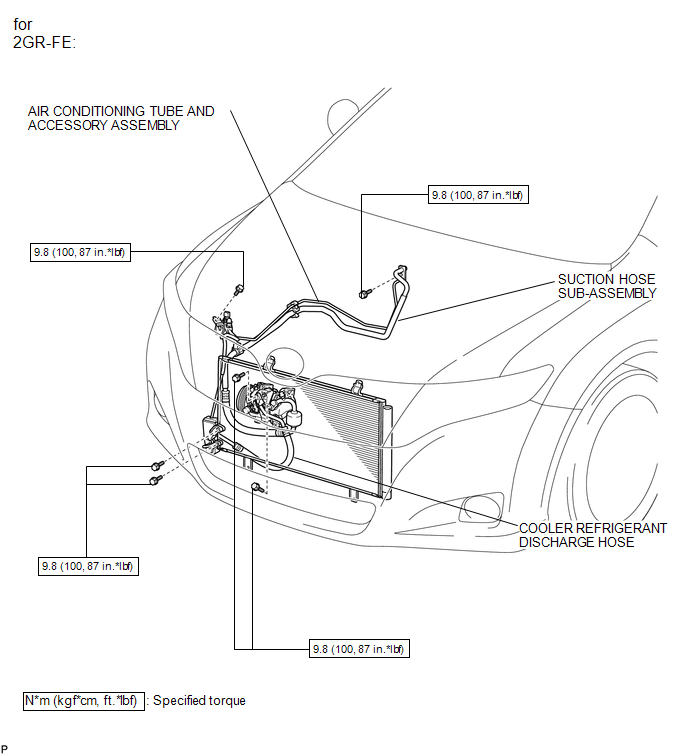
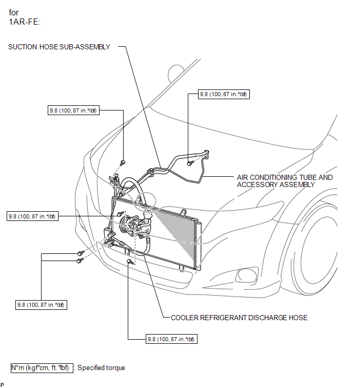
COMPONENTS
ILLUSTRATION
ILLUSTRATION
 Replacement
REPLACEMENT
PROCEDURE
1. RECOVER REFRIGERANT FROM REFRIGERATION SYSTEM
(a) Start up the engine.
(b) Turn the A/C switch on.
(c) Operate the cooler compressor at an engine speed of approximately 1 ...
 Room Temperature Sensor
Components
COMPONENTS
ILLUSTRATION
Removal
REMOVAL
PROCEDURE
1. DISCONNECT CABLE FROM NEGATIVE BATTERY TERMINAL
NOTICE:
When disconnecting the cable, some systems need to be initialized ...
Other materials about Toyota Venza:
Reverse Shift-linked Function of Power Mirrors does not Operate
SYSTEM DESCRIPTION
On receiving a reverse signal from the park/neutral position switch assembly,
the ECM sends the reverse signal to the main body ECU (driver side junction block
assembly) via CAN communication. When receiving the reverse signal, the main ...
Precaution
PRECAUTION
1. PRECAUTION FOR DISCONNECTING THE BATTERY CABLE
NOTICE:
When disconnecting the cable from the negative (-) battery terminal, initialize
the following systems after the cable is reconnected:
System
See Procedure
...
Intuitive parking assist
The distance from your vehicle to nearby obstacles when parallel parking or
maneuvering into a garage is measured by the sensors and communicated via the multi-information
display and a buzzer.
Always check the surrounding area when using this system.
&n ...

0.1535