Toyota Venza: Room Temperature Sensor
Components
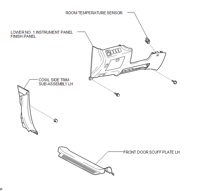
COMPONENTS
ILLUSTRATION
Removal
REMOVAL
PROCEDURE
1. DISCONNECT CABLE FROM NEGATIVE BATTERY TERMINAL
NOTICE:
When disconnecting the cable, some systems need to be initialized after the cable
is reconnected (See page .gif) ).
).
2. REMOVE FRONT DOOR SCUFF PLATE LH
3. REMOVE COWL SIDE TRIM SUB-ASSEMBLY LH
4. REMOVE LOWER NO. 1 INSTRUMENT PANEL FINISH PANEL
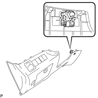
5. REMOVE ROOM TEMPERATURE SENSOR
|
(a) Disengage the 2 claws and remove the room temperature sensor. |
|
Inspection
INSPECTION
PROCEDURE
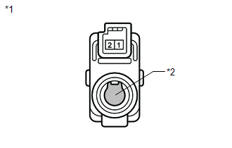
1. INSPECT ROOM TEMPERATURE SENSOR
(a) Measure the resistance according to the value(s) in the table below.
Standard Resistance:
|
Tester Connection |
Condition |
Specified Condition |
|---|---|---|
|
1 - 2 |
10°C (50°F) |
3.00 to 3.73 kΩ |
|
1 - 2 |
15°C (59°F) |
2.45 to 2.88 kΩ |
|
1 - 2 |
20°C (68°F) |
1.95 to 2.30 kΩ |
|
1 - 2 |
25°C (77°F) |
1.60 to 1.80 kΩ |
|
1 - 2 |
30°C (86°F) |
1.28 to 1.47 kΩ |
|
1 - 2 |
35°C (95°F) |
1.00 to 1.22 kΩ |
|
1 - 2 |
40°C (104°F) |
0.80 to 1.00 kΩ |
|
1 - 2 |
45°C (113°F) |
0.65 to 0.85 kΩ |
|
1 - 2 |
50°C (122°F) |
0.50 to 0.70 kΩ |
|
1 - 2 |
55°C (131°F) |
0.44 to 0.60 kΩ |
|
1 - 2 |
60°C (140°F) |
0.36 to 0.50 kΩ |
NOTICE:
- Hold the sensor only by its connector. Touching the sensor may change the resistance value.
- When measuring, the sensor temperature must be the same as the ambient temperature.
HINT:
As the temperature increases, the resistance decreases (see the graph).
If the resistance is not as specified, replace the room temperature sensor.
Text in Illustration|
*1 |
Component without harness connected (Room Temperature Sensor) |
|
*2 |
Sensing Portion |
.png)
Installation
INSTALLATION
PROCEDURE
1. INSTALL ROOM TEMPERATURE SENSOR
|
(a) Engage the 2 claws to install the room temperature sensor. |
|
.png)
2. INSTALL LOWER NO. 1 INSTRUMENT PANEL FINISH PANEL
.gif)
3. INSTALL COWL SIDE TRIM SUB-ASSEMBLY LH
4. INSTALL FRONT DOOR SCUFF PLATE LH
5. CONNECT CABLE TO NEGATIVE BATTERY TERMINAL
NOTICE:
When disconnecting the cable, some systems need to be initialized after the cable
is reconnected (See page ).
 Refrigerant Line
Components
COMPONENTS
ILLUSTRATION
ILLUSTRATION
...
 Solar Sensor
Components
COMPONENTS
ILLUSTRATION
On-vehicle Inspection
ON-VEHICLE INSPECTION
PROCEDURE
1. INSPECT SOLAR SENSOR
(a) Disconnect the solar sensor connector.
...
Other materials about Toyota Venza:
Satellite Radio Broadcast cannot be Received
CAUTION / NOTICE / HINT
NOTICE:
Some satellite radio broadcasts require payment. A contract must be made between
a satellite radio company and the user. If the contract expires, it will not be
possible to listen to the broadcast.
PROCEDURE
1 ...
ECU Version Miss Match (C1288/88)
DESCRIPTION
DTC Code
DTC Detection Condition
Trouble Area
C1288/88
ECM does not match.
ECM
PROCEDURE
1.
CHECK CAN COMMUNICATION SYSTEM
(a) Chec ...
Door Control Switch
Components
COMPONENTS
ILLUSTRATION
Inspection
INSPECTION
PROCEDURE
1. INSPECT DOOR CONTROL SWITCH ASSEMBLY
(a) Measure the resistance according to the value(s) in the table below.
Standard Resistance:
Tester Conn ...

0.1296