Toyota Venza: Reassembly
REASSEMBLY
PROCEDURE
1. INSTALL SHIFT SOLENOID VALVE SL4
|
(a) Coat the shift solenoid valve SL4 and bolt with ATF. Text in Illustration
|
|
.png)
(b) Install the shift solenoid valve SL4 and lock plate to the valve body assembly with the bolt.
Torque:
11 N·m {112 kgf·cm, 8 ft·lbf}
2. INSTALL SHIFT SOLENOID VALVE SL3
|
(a) Coat the shift solenoid valve SL3 and bolt with ATF. Text in Illustration
|
|
.png)
(b) Install the shift solenoid valve SL3 and lock plate to the valve body assembly with the bolt.
Torque:
11 N·m {112 kgf·cm, 8 ft·lbf}
3. INSTALL SHIFT SOLENOID VALVE SL1
|
(a) Coat the shift solenoid valve SL1 with ATF. Text in Illustration
|
|
.png)
(b) Install the shift solenoid valve SL1 to the valve body assembly.
4. INSTALL SHIFT SOLENOID VALVE SL2
(a) Coat the shift solenoid valve SL2 and bolt with ATF.
(b) Install the shift solenoid valve SL2 and lock plate to the valve body assembly with the bolt.
Torque:
11 N·m {112 kgf·cm, 8 ft·lbf}
5. INSTALL SHIFT SOLENOID VALVE SLU
|
(a) Coat the shift solenoid valve SLU with ATF. Text in Illustration
|
|
.png)
(b) Install the shift solenoid valve SLU to the valve body assembly.
6. INSTALL SHIFT SOLENOID VALVE SLT
(a) Coat the shift solenoid valve SLT with ATF.
(b) Install the shift solenoid valve SLT and lock plate to the valve body assembly.
7. INSTALL SHIFT SOLENOID VALVE SL
|
(a) Coat the shift solenoid valve SL with ATF. |
|
.png)
(b) Install the shift solenoid valve SL to the valve body assembly.
8. INSTALL ATF TEMPERATURE SENSOR ASSEMBLY
|
(a) Coat a new O-ring with ATF and install it to the ATF temperature sensor assembly. Text in Illustration
|
|
.png)
|
(b) Coat the 4 bolts with ATF. Text in Illustration
|
|
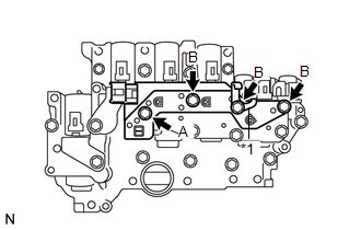
(c) Install the ATF temperature sensor assembly and clamp to the valve body assembly with the 4 bolts.
Torque:
11 N·m {112 kgf·cm, 8 ft·lbf}
Bolt length:
Bolt A
25 mm (0.984 in.)
Bolt B
85 mm (3.35 in.)
9. INSTALL TRANSMISSION WIRE
.gif)
 Inspection
INSPECTION
PROCEDURE
1. INSPECT SHIFT SOLENOID VALVE SL
(a) Measure the resistance according to the value(s) in the table below.
Text in Illustration
*1
...
 Installation
INSTALLATION
PROCEDURE
1. INSTALL MANUAL VALVE
(a) Coat the manual valve with ATF and install it to the transmission
valve body assembly.
...
Other materials about Toyota Venza:
Fuel pump shut off system
To minimize the risk of fuel leakage when the engine stalls or an airbag inflates
upon collision, the fuel pump shut off system stops supplying fuel to the engine.
Follow the procedure below to restart the engine after the system is activated.
►Vehic ...
Precaution
PRECAUTION
NOTICE:
When disconnecting the cable from the negative (-) battery terminal, initialize
the following systems after the cable is reconnected.
System Name
See Procedure
Back Door Closer System
...
Installation
INSTALLATION
PROCEDURE
1. INSPECT TORQUE CONVERTER ASSEMBLY
2. INSTALL TORQUE CONVERTER ASSEMBLY
(a) Engage the splines of the input shaft and turbine runner.
(b) Engage the splines o ...

0.1339