Toyota Venza: Inspection
INSPECTION
PROCEDURE
1. INSPECT SHIFT SOLENOID VALVE SL
|
(a) Measure the resistance according to the value(s) in the table below. Text in Illustration
Standard Resistance:
If the value is not as specified, replace the shift solenoid valve. |
|
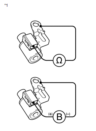
(b) Connect a positive (+) battery lead to the terminal of the solenoid connector, and a negative (-) battery lead to the solenoid body, and check the operation of the valve.
NOTICE:
When using battery voltage during the inspection, do not bring the positive (+) and negative (-) tester probes too close to each other as a short circuit may occur.
OK:
The valve moves and makes an operating sound.
If the operation cannot be done as specified, replace the shift solenoid valve.
2. INSPECT SHIFT SOLENOID VALVE SLT
|
(a) Measure the resistance according to the value(s) in the table below. Text in Illustration
Standard Resistance:
If the value is not as specified, replace the shift solenoid valve. |
|
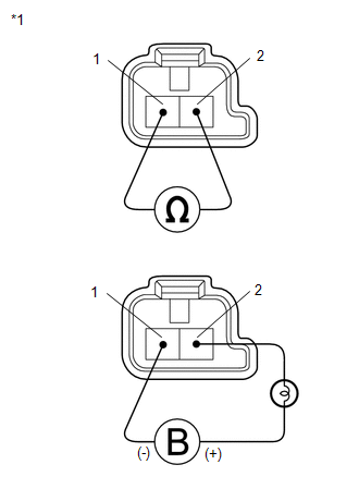
(b) Connect a positive (+) battery lead with a 21 W bulb to terminal 2 and a negative (-) battery lead to terminal 1 of the solenoid valve connector, and check the operation of the valve.
NOTICE:
When using battery voltage during the inspection, do not bring the positive (+) and negative (-) tester probes too close to each other as a short circuit may occur.
OK:
The valve moves and makes an operating sound.
If the operation cannot be done as specified, replace the shift solenoid valve.
3. INSPECT SHIFT SOLENOID VALVE SLU
|
(a) Measure the resistance according to the value(s) in the table below. Text in Illustration
Standard Resistance:
If the value is not as specified, replace the shift solenoid valve. |
|
(b) Connect a positive (+) battery lead with a 21 W bulb to terminal 2 and a negative (-) battery lead to terminal 1 of the solenoid valve connector, and check the operation of the valve.
NOTICE:
When using battery voltage during the inspection, do not bring the positive (+) and negative (-) tester probes too close to each other as a short circuit may occur.
OK:
The valve moves and makes an operating sound.
If the operation cannot be done as specified, replace the shift solenoid valve.
4. INSPECT SHIFT SOLENOID VALVE SL1
|
(a) Measure the resistance according to the value(s) in the table below. Text in Illustration
Standard Resistance:
If the value is not as specified, replace the shift solenoid valve. |
|
(b) Connect a positive (+) battery lead with a 21 W bulb to terminal 2 and a negative (-) battery lead to terminal 1 of the solenoid valve connector, and check the operation of the valve.
NOTICE:
When using battery voltage during the inspection, do not bring the positive (+) and negative (-) tester probes too close to each other as a short circuit may occur.
OK:
The valve moves and makes an operating sound.
If the operation cannot be done as specified, replace the shift solenoid valve.
5. INSPECT SHIFT SOLENOID VALVE SL2
|
(a) Measure the resistance according to the value(s) in the table below. Text in Illustration
Standard Resistance:
If the value is not as specified, replace the shift solenoid valve. |
|
(b) Connect a positive (+) battery lead with a 21 W bulb to terminal 2 and a negative (-) battery lead to terminal 1 of the solenoid valve connector, and check the operation of the valve.
NOTICE:
When using battery voltage during the inspection, do not bring the positive (+) and negative (-) tester probes too close to each other as a short circuit may occur.
OK:
The valve moves and makes an operating sound.
If the operation cannot be done as specified, replace the shift solenoid valve.
6. INSPECT SHIFT SOLENOID VALVE SL3
|
(a) Measure the resistance according to the value(s) in the table below. Text in Illustration
Standard Resistance:
If the value is not as specified, replace the shift solenoid valve. |
|
(b) Connect a positive (+) battery lead with a 21 W bulb to terminal 2 and a negative (-) battery lead to terminal 1 of the solenoid valve connector, and check the operation of the valve.
NOTICE:
When using battery voltage during the inspection, do not bring the positive (+) and negative (-) tester probes too close to each other as a short circuit may occur.
OK:
The valve moves and makes an operating sound.
If the operation cannot be done as specified, replace the shift solenoid valve.
7. INSPECT SHIFT SOLENOID VALVE SL4
|
(a) Measure the resistance according to the value(s) in the table below. Text in Illustration
Standard Resistance:
If the value is not as specified, replace the shift solenoid valve. |
|
(b) Connect a positive (+) battery lead with a 21 W bulb to terminal 2 and a negative (-) battery lead to terminal 1 of the solenoid valve connector, and check the operation of the valve.
NOTICE:
When using battery voltage during the inspection, do not bring the positive (+) and negative (-) tester probes too close to each other as a short circuit may occur.
OK:
The valve moves and makes an operating sound.
If the operation cannot be done as specified, replace the shift solenoid valve.
 Removal
REMOVAL
PROCEDURE
1. REMOVE AUTOMATIC TRANSAXLE ASSEMBLY
HINT:
See the steps from "Remove Engine Assembly with transaxle" through "Remove Automatic
Transaxle Assembly" (See p ...
 Reassembly
REASSEMBLY
PROCEDURE
1. INSTALL SHIFT SOLENOID VALVE SL4
(a) Coat the shift solenoid valve SL4 and bolt with ATF.
Text in Illustration
*1
Lock Pla ...
Other materials about Toyota Venza:
Components
COMPONENTS
ILLUSTRATION
ILLUSTRATION
ILLUSTRATION
ILLUSTRATION
ILLUSTRATION
...
Problem Symptoms Table
PROBLEM SYMPTOMS TABLE
Use the table below to help determine the cause of problem symptoms.
If multiple suspected areas are listed, the potential causes of the symptoms
are listed in order of probability in the "Suspected Area" column ...
Inspection
INSPECTION
PROCEDURE
1. INSPECT COURTESY LIGHT SWITCH
(a) Measure the resistance according to the value(s) in the table below.
Standard Resistance:
Tester Connection
Switch Condition
Specified Condition
...

0.1622