Toyota Venza: Reassembly
REASSEMBLY
PROCEDURE
1. INSTALL BEARING BRACKET HOLE SNAP RING (for RH Side)
(a) Install a new bearing bracket hole snap ring to the front drive shaft assembly RH.
2. INSTALL FRONT DRIVE SHAFT BEARING (for RH Side)
|
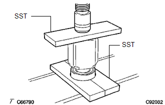
(a) Using SST, install a new front drive shaft bearing. SST: 09527-10011 SST: 09527-30010 NOTICE: The bearing should be completely installed. |
|
|
(b) Using a snap ring expander, install a new drive shaft hole snap ring. |
|
.png)
3. INSTALL FRONT DRIVE SHAFT DUST COVER (for 2WD RH Side)
|
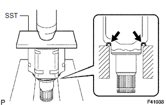
(a) Using SST and a press, install a new front drive shaft dust cover. SST: 09527-10011 SST: 09726-40010 Distance: 26.6 to 27.6 mm (1.05 to 1.09 in.) NOTICE:
|
|
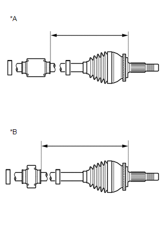
4. INSTALL FRONT DRIVE SHAFT DUST COVER RH (for 2WD RH Side)
|
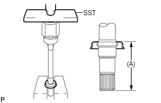
(a) Using SST and a press, install a new front drive shaft dust cover RH until the distance (A) from the tip of the center drive shaft to the front drive shaft dust cover RH meets the specification. SST: 09527-10011 Distance (A)
NOTICE:
|
|
5. INSTALL FRONT DRIVE SHAFT DUST COVER LH (for LH Side)
|
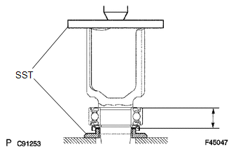
(a) Using SST and a press, install a new front drive shaft dust cover LH. SST: 09527-10011 NOTICE:
|
|
6. INSTALL FRONT AXLE OUTBOARD JOINT BOOT
|
(a) Wrap the spline of the drive shaft with vinyl tape to prevent the boot from being damaged. Text in Illustration
|
|
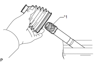
(b) Install new parts to the front drive outboard joint shaft assembly in the following order:
(1) No. 2 front axle outboard joint boot clamp
(2) Front axle outboard joint boot
(3) Front axle outboard joint boot clamp
(c) Pack the front drive outboard joint shaft assembly and front axle outboard joint boot with grease from the boot kit.
Grease capacity:
164 to 184 g (5.8 to 6.4 oz.)
7. INSTALL FRONT AXLE OUTBOARD JOINT BOOT CLAMP
(a) Hold the drive shaft lightly in a vise between aluminum plates.
NOTICE:
Do not overtighten the vise.
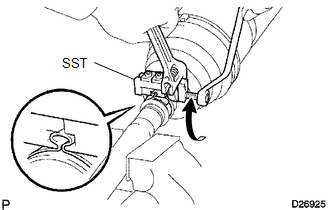
(b) Install the front axle outboard joint boot clamp onto the front axle outboard joint boot.
|
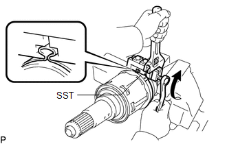
(c) Place SST onto the front axle outboard joint boot clamp. SST: 09521-24010 |
|
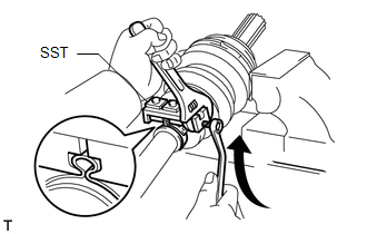
(d) Tighten SST so that the front axle outboard joint boot clamp is pinched.
NOTICE:
Do not overtighten SST.
|
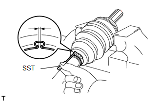
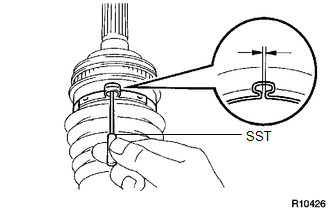
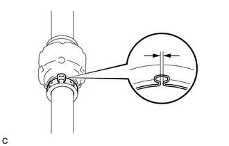
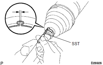
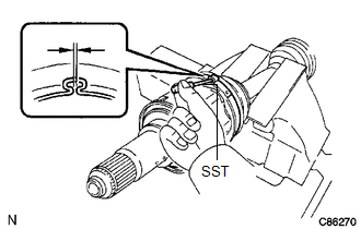
(e) Using SST, measure the clearance of the front axle outboard joint boot clamp. SST: 09240-00020 Clearance: 0.5 to 1.5 mm (0.0197 to 0.0591 in.) NOTICE: If the measured value is greater than the specified value, retighten the clamp. |
|
8. INSTALL NO. 2 FRONT AXLE OUTBOARD JOINT BOOT CLAMP
(a) Install the No. 2 front axle outboard joint boot clamp onto the front axle outboard joint boot.
|
(b) Place SST onto the No. 2 front axle outboard joint boot clamp. SST: 09521-24010 |
|
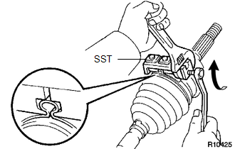
(c) Tighten SST so that the No. 2 front axle outboard joint boot clamp is pinched.
NOTICE:
Do not overtighten SST.
|
(d) Using SST, measure the clearance of the No. 2 front axle outboard joint boot clamp. SST: 09240-00020 Clearance: 0.5 to 1.5 mm (0.0197 to 0.0591 in.) NOTICE: If the measured value is greater than the specified value, retighten the clamp. |
|
9. INSTALL FRONT DRIVE SHAFT DAMPER (w/ 1 Clamp)
|
(a) Install the front drive shaft damper to the drive shaft. NOTICE: Make sure that the damper is on the shaft groove. |
|
(b) Set the distance as specified below.
Distance|
for 1AR-FE |
LH |
237 to 241 mm (9.34 to 9.48 in.) |
|
RH |
231 to 235 mm (9.09 to 9.25 in.) |
|
|
for 2GR-FE |
LH |
237 to 241 mm (9.33 to 9.49 in.) |
|
RH |
234 to 238 mm (9.21 to 9.37 in.) |
(c) Install a new front drive shaft damper clamp onto the front drive shaft damper.
NOTICE:
Be sure to install the clamp in the correct position.
|
(d) Place SST onto the front drive shaft damper clamp. SST: 09521-24010 |
|
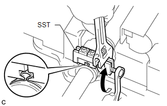
(e) Tighten SST so that the clamp is pinched.
NOTICE:
Do not overtighten SST.
|
(f) Using SST, measure the clearance of the front drive shaft damper clamp. SST: 09240-00020 Clearance: 0.5 to 1.5 mm (0.0197 to 0.0591 in.) NOTICE: If the measured value is greater than the specified value, retighten the clamp. |
|
10. INSTALL FRONT DRIVE SHAFT DAMPER (w/ 2 Clamps)
|
(a) Temporarily install the front drive shaft damper and 2 new front drive shaft damper clamps as shown in the illustration. Text in Illustration
|
|
|||||||||||||
|
(b) Using needle-nose pliers, install the 2 front drive shaft damper clamps as shown in the illustration. |
|
.png)
11. INSTALL FRONT DRIVE INBOARD JOINT ASSEMBLY
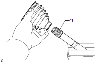
(a) Wrap the spline of the outboard joint shaft with vinyl tape to prevent the boot from being damaged.
|
(b) Install new parts to the front drive outboard joint shaft assembly in the following order: Text in Illustration
(1) Front axle inboard joint boot clamp (2) Front axle inboard joint boot (3) No. 2 front axle inboard joint boot clamp |
|
|
(c) Place the beveled side of the tripod joint axial spline toward the front drive outboard joint shaft assembly. Text in Illustration
|
|
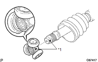
(d) Align the matchmarks placed before removal.
(e) Using a brass bar and a hammer, tap in the tripod joint to the front drive outboard joint shaft assembly.
NOTICE:
- Do not tap the roller.
- Be sure to install the tripod joint in the correct direction.
|
(f) Using a snap ring expander, install a new shaft snap ring. |
|
.png)
(g) Pack the front drive inboard joint assembly and front axle inboard boot with grease.
Grease capacity:
|
for 1AR-FE |
for 2GR-FE |
|---|---|
|
135 to 155 g (4.8 to 5.4 oz.) |
155 to 175 g (5.5 to 6.1 oz.) |
|
(h) Align the matchmarks and install the front drive inboard joint assembly to the front drive outboard joint shaft assembly. Text in Illustration
|
|

12. INSTALL FRONT AXLE INBOARD JOINT BOOT
(a) Install the front axle inboard joint boot to the front drive inboard joint assembly.
|
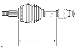
(b) Check whether the drive shaft dimensions are within the following specifications. Text in Illustration
HINT: The following table shows the dimension (A) of the drive shaft. Dimension (A) for 1AR-FE
|
|
.png)
13. INSTALL FRONT AXLE INBOARD JOINT BOOT CLAMP
(a) Hold the drive shaft lightly in a vise between aluminum plates.
NOTICE:
Do not overtighten the vise.
(b) Secure the front axle inboard joint boot clamp onto the front axle inboard joint boot.
|
(c) Place SST onto the front axle inboard joint boot clamp. SST: 09521-24010 |
|
(d) Tighten SST so that the front axle inboard joint boot clamp is pinched.
NOTICE:
Do not overtighten SST.
|
(e) Using SST, measure the clearance of the front axle inboard joint boot clamp. SST: 09240-00020 Clearance: 0.5 to 1.5 mm (0.0197 to 0.0591 in.) NOTICE: If the measured value is greater than the specified value, retighten the clamp. |
|
14. INSTALL NO. 2 FRONT AXLE INBOARD JOINT BOOT CLAMP (for 1AR-FE)
|
(a) Using needle-nose pliers, engage the 2 claws to install the No. 2 front axle inboard joint boot clamp as shown in the illustration. |
|
.png)
15. INSTALL NO. 2 FRONT AXLE INBOARD JOINT BOOT CLAMP (for 2GR-FE)
(a) Hold the front drive inboard joint shaft assembly in a vise between aluminum plates.
NOTICE:
Do not overtighten the vise.
(b) Secure the No. 2 front axle inboard joint boot clamp onto the front axle inboard joint boot.
|
(c) Place SST onto the No. 2 front axle inboard joint boot clamp. SST: 09521-24010 |
|
(d) Tighten SST so that the No. 2 front axle inboard joint boot clamp is pinched.
NOTICE:
Do not overtighten SST.
|
(e) Using SST, measure the clearance of the No. 2 front axle inboard joint boot clamp. SST: 09240-00020 Clearance: 0.5 to 1.5 mm (0.0197 to 0.0591 in.) NOTICE: If the measured value is greater than the specified value, retighten the clamp. |
|
16. INSTALL FRONT DRIVE SHAFT HOLE SNAP RING
(a) Install a new front drive shaft hole snap ring.
17. INSPECT FRONT DRIVE SHAFT ASSEMBLY LH
.gif)
 Inspection
INSPECTION
PROCEDURE
1. INSPECT FRONT DRIVE SHAFT ASSEMBLY
(a) Check whether the drive shaft dimensions are within the following
specifications.
Text in Illustration
...
 Installation
INSTALLATION
PROCEDURE
1. INSTALL FRONT DRIVE SHAFT ASSEMBLY LH
(a) Align the splines of the shaft and install the drive shaft assembly
LH using a brass bar and a hammer.
NOT ...
Other materials about Toyota Venza:
Intuitive parking assist
The distance from your vehicle to nearby obstacles when parallel parking or
maneuvering into a garage is measured by the sensors and communicated via the multi-information
display and a buzzer.
Always check the surrounding area when using this system.
&n ...
Entry Answer-back Buzzer does not Sound
DESCRIPTION
The smart key system uses the wireless door lock buzzer to perform various vehicle
exterior warnings. When the conditions for each warning are met, the certification
ECU (smart key ECU assembly) sends a buzzer request signal to the main body E ...
Power Window Switch Malfunction (B2312)
DESCRIPTION
The power window regulator motor assembly is operated by the power window regulator
master switch assembly or power window regulator switch assembly. The power window
regulator motor assembly has motor, regulator and ECU functions.
This DTC i ...

0.1404