Toyota Venza: Reassembly
REASSEMBLY
PROCEDURE
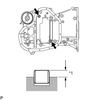
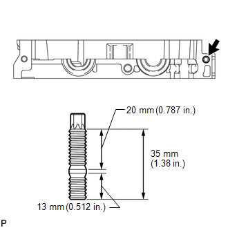
1. INSTALL STIFFENING CRANKCASE RING PIN
NOTICE:
It is not necessary to remove the ring pin unless it is being replaced.
|
(a) Using a plastic-faced hammer, tap in 2 new ring pins until they stop. Text in Illustration
Standard protrusion height: 4.3 to 5.3 mm (0.169 to 0.209 in.) |
|
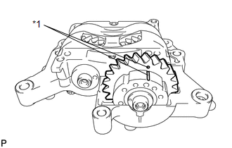
2. INSTALL ENGINE BALANCER ASSEMBLY
(a) Check that the alignment marks of the balance shaft damper cover and balance shaft driven gear are aligned.
 Text in Illustration
|
*1 |
Alignment Mark |
If the alignment marks are not aligned, realign them.
|
(1) Place a wrench on the rear cutout part of the No. 2 balance shaft and secure the shaft in place. Text in Illustration
|
|
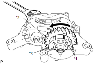
(2) Rotate the balance shaft driven gear of the No. 1 balance shaft counterclockwise to align the alignment mark of the balance shaft driven gear with the alignment mark of the balance shaft damper cover.
|
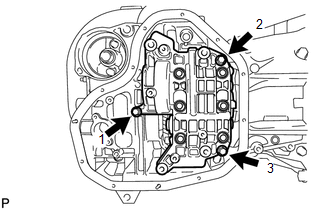
(b) Install the engine balancer to the stiffening crankcase with the 3 bolts, and tighten the bolts in the sequence shown in the illustration. Torque: 24 N·m {245 kgf·cm, 18 ft·lbf} |
|
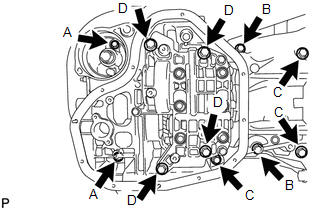
3. INSTALL STIFFENING CRANKCASE STUD BOLT
NOTICE:
If a stud bolt is deformed or the threads are damaged, replace it.
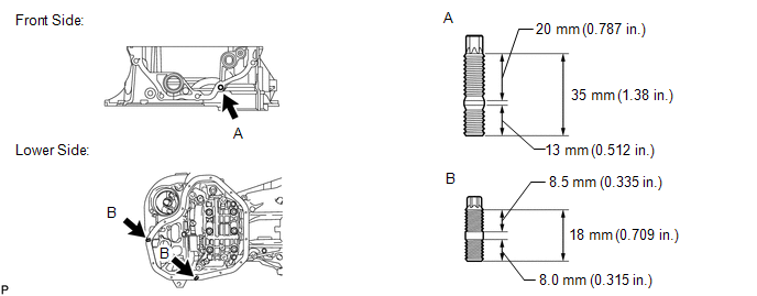
(a) Using an E5 and E8 "TORX" socket wrenches, install the stud bolts.
Torque:
for stud bolt A :
5.0 N·m {51 kgf·cm, 44 in·lbf}
for stud bolt B :
4.0 N·m {41 kgf·cm, 35 in·lbf}
4. INSTALL STIFFENING CRANKCASE ASSEMBLY
|
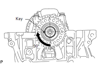
(a) Rotate the crankshaft clockwise so that the crankshaft key is at the position 90° from the bottom as shown in the illustration. |
|
|
(b) Apply seal packing in a continuous line as shown in the illustration. Seal packing: Toyota Genuine Seal Packing Black, Three Bond 1207B or equivalent Standard Seal Dimension:
Application Length A: 28 mm (1.10 in.) NOTICE:
|
|
|
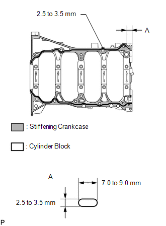
(c) Check that the rear cutout parts are as shown in the illustration. Text in Illustration
|
|
(d) Clean the bolts and their installation holes.
|
(e) Apply adhesive to 3 threads or more of the end of bolt A. Adhesive: Toyota Genuine Adhesive 1344, Three Bond 1344 or equivalent |
|

|
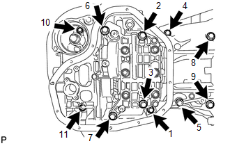
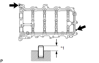
(f) Temporarily install the stiffening crankcase with the 11 bolts. Bolt Length :
HINT: Apply adhesive to bolt A before installing it. |
|
|
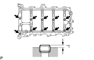
(g) Tighten the 11 bolts in the sequence shown in the illustration to install the stiffening crankcase Torque: for Bolt A : 24 N·m {245 kgf·cm, 18 ft·lbf} except Bolt A : 43 N·m {438 kgf·cm, 32 ft·lbf} |
|
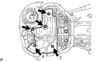
5. INSTALL NO. 1 OIL PAN BAFFLE PLATE
|
(a) Install the oil pan baffle plate and uniformly tighten the 5 bolts in several steps, in the sequence shown in the illustration. Torque: 10 N·m {102 kgf·cm, 7 ft·lbf} |
|
6. INSTALL OIL STRAINER SUB-ASSEMBLY
(a) Apply a light coat of engine oil to a new gasket.
|
(b) Align the protrusion of the gasket with the cutout of the oil strainer, and install the gasket to the oil strainer. |
|
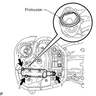
(c) Install the oil strainer with the 3 bolts in several steps, in the sequence shown in the illustration.
Torque:
10 N·m {102 kgf·cm, 7 ft·lbf}
7. INSTALL OIL PAN SUB-ASSEMBLY
|
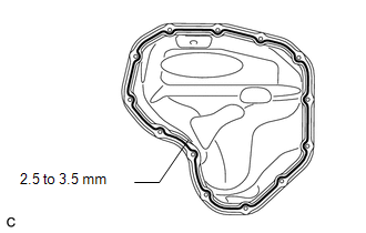
(a) Apply seal packing in a continuous line as shown in the illustration. Seal packing: Toyota Genuine Seal Packing Black, Three Bond 1207B or equivalent Standard seal diameter: 2.5 to 3.5 mm (0.0984 to 0.138 in.) NOTICE:
|
|
|
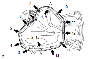
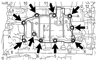
(b) Install the oil pan with the 11 bolts and 2 nuts in several steps, in the sequence shown in the illustration. Torque: 10 N·m {102 kgf·cm, 7 ft·lbf} HINT: Bolt A and nut A are tightened twice. |
|
8. INSTALL OIL FILTER BRACKET CLIP
(a) Install the oil filter bracket clip to the stiffening crankcase assembly.
9. INSTALL OIL FILTER CAP ASSEMBLY
.gif)
10. INSTALL REAR ENGINE OIL SEAL
11. INSTALL CYLINDER BLOCK WATER JACKET SPACER
|
(a) Install the water jacket spacer to the cylinder block. |
|
.png)
12. INSTALL CYLINDER HEAD GASKET
13. INSTALL CYLINDER HEAD SUB-ASSEMBLY
14. SET CAMSHAFT TIMING GEAR ASSEMBLY
15. INSTALL CAMSHAFT BEARING CAP SETTING RING PIN
NOTICE:
It is not necessary to remove the ring pin unless it is being replaced.
|
(a) Using a plastic-faced hammer, tap in 10 new ring pins to the camshaft housing. Text in Illustration
Standard protrusion height: 2.7 to 3.3 mm (0.106 to 0.130 in.) |
|
16. INSTALL CAMSHAFT HOUSING STRAIGHT PIN
NOTICE:
It is not necessary to remove the straight pin unless it is being replaced.
|
(a) Using a plastic-faced hammer, tap in 2 new straight pins to the camshaft housing. Text in Illustration
Standard protrusion height: 5.0 to 7.0 mm (0.197 to 0.276 in.) |
|
17. INSTALL CAMSHAFT HOUSING STUD BOLT
NOTICE:
If a stud bolt is deformed or the threads are damaged, replace it.
|
(a) Using an E8 "TORX" socket wrench, install the stud bolt. Torque: 6.5 N·m {66 kgf·cm, 58 in·lbf} |
|
18. INSTALL NO. 1 CAMSHAFT BEARING
|
(a) Clean the No. 1 camshaft bearing. |
|
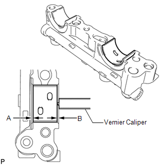
(b) Install the camshaft bearing to the No. 1 camshaft bearing cap.
(c) Using a vernier caliper, measure the distance between the camshaft bearing cap edge and the camshaft bearing edge.
Standard dimension A - B or B - A:
0 to 0.7 mm (0 to 0.0276 in.)
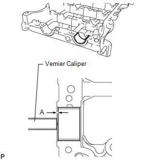
19. INSTALL NO. 2 CAMSHAFT BEARING
(a) Clean the No. 2 camshaft bearing.
(b) Install the camshaft bearing to the camshaft housing.
|
(c) Using a vernier caliper, measure the distance between the camshaft housing edge and the camshaft bearing edge. Standard distance: 1.15 to 1.85 mm (0.0453 to 0.0728 in.) |
|
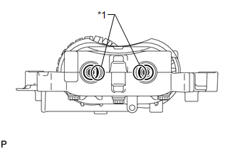
20. INSTALL OIL CONTROL VALVE FILTER
|
(a) Install the oil control valve filter to the No. 1 camshaft bearing cap. |
|
.png)
21. INSTALL CAMSHAFT
22. INSTALL CAMSHAFT BEARING CAP
23. INSTALL VALVE STEM CAP
24. INSTALL VALVE LASH ADJUSTER ASSEMBLY
25. INSTALL NO. 1 VALVE ROCKER ARM SUB-ASSEMBLY
26. INSTALL CAMSHAFT HOUSING SUB-ASSEMBLY
27. INSTALL CAMSHAFT TIMING GEAR ASSEMBLY
28. INSTALL CAMSHAFT TIMING EXHAUST GEAR ASSEMBLY
29. INSTALL CRANKSHAFT TIMING SPROCKET
|
(a) Install the crankshaft timing sprocket to the crankshaft. |
|
.png)
30. ADD ENGINE OIL
31. SET NO. 1 CYLINDER TO TDC/COMPRESSION
32. INSTALL NO. 1 CHAIN VIBRATION DAMPER
33. INSTALL CHAIN SUB-ASSEMBLY
34. INSTALL CHAIN TENSIONER SLIPPER
35. INSTALL NO. 1 CHAIN TENSIONER ASSEMBLY
36. INSTALL TIMING CHAIN GUIDE
37. CHECK NO. 1 CYLINDER TO TDC/COMPRESSION
38. INSTALL TIMING CHAIN COVER PLATE
|
(a) Install a new gasket and the timing chain cover plate with the 4 bolts. Torque: 10 N·m {102 kgf·cm, 7 ft·lbf} |
|
.png)
39. INSTALL TIMING CHAIN COVER TIGHT PLUG
|
(a) Using a 14 mm hexagon wrench, install a new gasket and the plug. Torque: 30 N·m {306 kgf·cm, 22 ft·lbf} |
|
.png)
40. INSTALL TIMING CHAIN COVER SUB-ASSEMBLY
41. INSTALL ENGINE MOUNTING BRACKET RH
42. INSTALL TIMING CHAIN COVER OIL SEAL
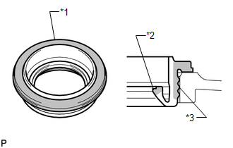
43. INSTALL SPARK PLUG TUBE GASKET
|
(a) Visually check the spark plug tube gasket. OK:
If the result is not as specified, replace the spark plug tube gasket. Text in Illustration
|
|
|
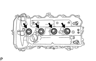
(b) Install the 4 plug tube gaskets to the cylinder head cover. NOTICE: After pressing in the spark plug tube gasket, make sure the gasket protrudes 1.0 mm (0.0394 in.) or less from the cylinder head cover. |
|
44. INSTALL CYLINDER HEAD COVER SUB-ASSEMBLY
|
(a) Apply a light coat of engine oil to 3 new gaskets. |
|
.png)
(b) Install the 3 gaskets to the camshaft bearing caps.
(c) Install a new gasket to the cylinder head cover.
NOTICE:
Remove any oil from the contact surfaces.
|
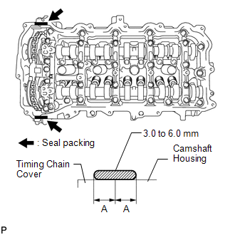
(d) Apply seal packing as shown in the illustration. Seal packing: Toyota Genuine Seal Packing Black, Three Bond 1207B or equivalent Standard seal diameter: 3.0 to 6.0 mm (0.118 to 0.236 in.) Application width A: 5.0 mm (0.197 in.) NOTICE:
|
|
|
(e) Align the cylinder head cover with pin A. Then align the cylinder head cover with pin B and install the cylinder head cover. |
|
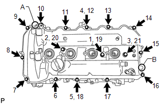
(f) Install 3 new seal washers and the 16 bolts, and then tighten the bolts in the order shown in the illustration.
Torque:
12 N·m {122 kgf·cm, 9 ft·lbf}
NOTICE:
Do not apply oil for at least 4 hours after the installation.
45. INSTALL CRANKSHAFT PULLEY
|
(a) Align the pulley set key with the key groove of the crankshaft pulley. |
|
.png)
(b) Using SST, hold the crankshaft pulley and install the pulley bolt.
SST: 09213-54015
SST: 09330-00021
Torque:
260 N·m {2651 kgf·cm, 192 ft·lbf}
HINT:
Part number of installation bolt for SST (crankshaft pulley holding tool): 91551-80650 (quantity: 2)
46. INSTALL CRANKSHAFT POSITION SENSOR
47. INSTALL INLET WATER HOUSING
|
(a) Install a new gasket and the inlet water housing with the 4 bolts and nut. Torque: 43 N·m {438 kgf·cm, 32 ft·lbf} |
|
.png)
48. INSTALL OIL COOLER ASSEMBLY (w/ Oil Cooler)
49. INSTALL WATER PUMP ASSEMBLY
50. INSTALL V-RIBBED BELT TENSIONER ASSEMBLY
|
(a) Install the V-ribbed belt tensioner with the bolt. Torque: 21 N·m {214 kgf·cm, 15 ft·lbf} |
|
.png)
51. INSTALL THERMOSTAT
52. INSTALL WATER INLET
53. INSTALL NO. 1 WATER BY-PASS PIPE
|
(a) Install a new gasket and the water by-pass pipe with the 2 nuts and bolt. Torque: 10 N·m {102 kgf·cm, 7 ft·lbf} |
|
.png)
54. INSTALL SEPARATOR CASE
|
(a) Apply a light coat of engine oil to a new gasket. |
|
.png)
(b) Install the gasket to the separator case.
(c) Install the separator case with the 2 bolts.
Torque:
10 N·m {102 kgf·cm, 7 ft·lbf}
55. INSTALL VENTILATION CASE SUB-ASSEMBLY
|
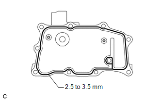
(a) Apply seal packing in a continuous line as shown in the illustration. Seal packing: Toyota Genuine Seal Packing Black, Three Bond 1207B or equivalent Standard seal diameter: 2.5 to 3.5 mm (0.0984 to 0.138 in.) NOTICE:
|
|
|
(b) Install the ventilation case, and install the 8 bolts and 2 nuts in the order shown in the illustration. Torque: 21 N·m {214 kgf·cm, 15 ft·lbf} HINT: Bolt A is tightened twice. |
|
56. INSTALL VENTILATION VALVE SUB-ASSEMBLY
57. INSTALL CAMSHAFT POSITION SENSOR (for Intake Side)
58. INSTALL CAMSHAFT POSITION SENSOR (for Exhaust Side)
59. INSTALL CAMSHAFT TIMING OIL CONTROL VALVE ASSEMBLY (for Intake Side)
60. INSTALL CAMSHAFT TIMING OIL CONTROL VALVE ASSEMBLY (for Exhaust Side)
61. INSTALL OIL FILLER CAP SUB-ASSEMBLY
(a) Install a new gasket to the oil filler cap.
(b) Install the oil filler cap to the cylinder head.
62. INSTALL SPARK PLUG
63. INSTALL ENGINE COVER JOINT
|
(a) Install the 3 joints. Torque: 10 N·m {102 kgf·cm, 7 ft·lbf} |
|
.png)
 Installation
INSTALLATION
CAUTION / NOTICE / HINT
HINT:
Perform "Inspection After Repair" after replacing the engine assembly (See page
).
PROCEDURE
1. INSTALL IGNITION COIL ASSEMBLY
2. INSTAL ...
 Front Crankshaft Oil Seal
Components
COMPONENTS
ILLUSTRATION
Removal
REMOVAL
PROCEDURE
1. REMOVE FRONT WHEEL RH
2. REMOVE NO. 1 ENGINE UNDER COVER
3. SEPARATE FRONT FENDER LINER RH
4. REMOVE FRONT FENDER APRON S ...
Other materials about Toyota Venza:
Reassembly
REASSEMBLY
PROCEDURE
1. INSTALL GENERATOR ROTOR ASSEMBLY
(a) Place the generator drive end frame on the generator pulley.
(b) Install the generator rotor to the generator drive end frame.
...
Disassembly
DISASSEMBLY
PROCEDURE
1. REMOVE BREATHER PLUG HOSE
(a) Using a screwdriver, remove the No. 2 breather plug (ATM) from the
transaxle case sub-assembly.
(b) Using a screwdriver, remove ...
Removal
REMOVAL
PROCEDURE
1. PRECAUTION
CAUTION:
Be sure to read Precaution thoroughly before servicing (See page
).
2. TURN FRONT WHEELS TO FACE STRAIGHT AHEAD
3. DISCONNECT CABLE FROM NEGATIVE BATTERY TERMINAL
CAUTION:
Wait at least 90 seconds after discon ...

0.1247