Toyota Venza: Front Crankshaft Oil Seal
Components
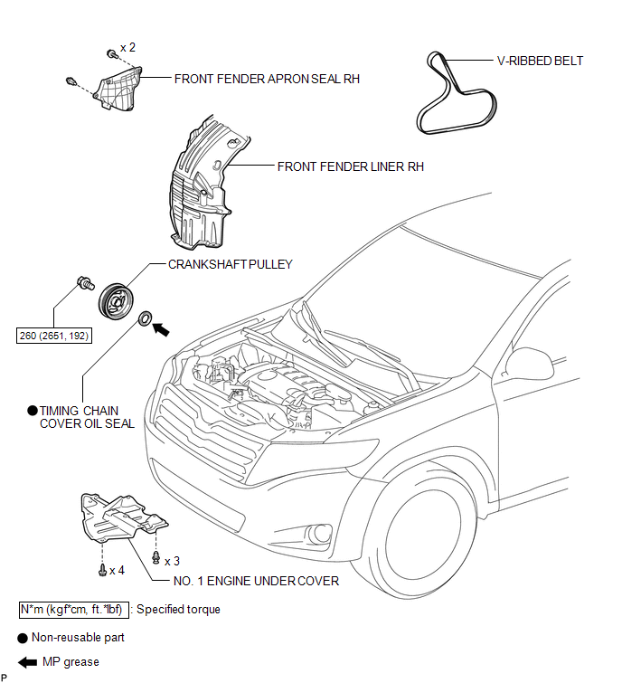
COMPONENTS
ILLUSTRATION
Removal
REMOVAL
PROCEDURE
1. REMOVE FRONT WHEEL RH
2. REMOVE NO. 1 ENGINE UNDER COVER
3. SEPARATE FRONT FENDER LINER RH
4. REMOVE FRONT FENDER APRON SEAL RH
.gif)
5. REMOVE V-RIBBED BELT
6. REMOVE CRANKSHAFT PULLEY
|
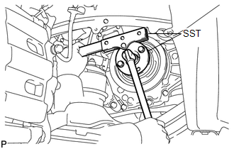
(a) Using SST, hold the crankshaft pulley and loosen the pulley bolt. Further loosen the bolt until 2 or 3 threads are screwed into the crankshaft. SST: 09213-54015 SST: 09330-00021 HINT: Part number of installation bolt for SST (crankshaft pulley holding tool): 91551-80650 (quantity: 2) |
|
|
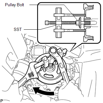
(b) Using SST and the pulley bolt, remove the crankshaft pulley. SST: 09950-50013 09951-05010 09952-05010 09953-05020 09954-05011 HINT: Apply a lubricant to the threads and end of SST. |
|
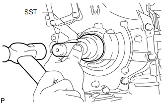
7. REMOVE TIMING CHAIN COVER OIL SEAL
|
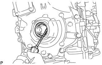
(a) Using a screwdriver, pry out the oil seal. HINT: Tape the screwdriver tip before use. NOTICE: Do not damage the surface of the oil seal press fit hole or the crankshaft. |
|
Installation
INSTALLATION
PROCEDURE
1. INSTALL TIMING CHAIN COVER OIL SEAL
(a) Apply MP grease to the lip of a new oil seal.
NOTICE:
- Do not allow foreign matter to contact the lip of the oil seal.
- Do not allow MP grease to contact the dust seal.
|
(b) Using SST and a hammer, tap in the oil seal until its surface is flush with the timing chain cover edge. SST: 09223-22010 NOTICE:
|
|
2. INSTALL CRANKSHAFT PULLEY
(a) Align the pulley set key with the key groove of the crankshaft pulley.
|
(b) Using SST, hold the crankshaft pulley and install the pulley bolt. SST: 09213-54015 SST: 09330-00021 Torque: 260 N·m {2651 kgf·cm, 192 ft·lbf} HINT: Part number of installation bolt for SST (crankshaft pulley holding tool): 91551-80650 (quantity: 2) |
|
.png)
3. INSTALL V-RIBBED BELT
.gif)
4. INSTALL FRONT FENDER APRON SEAL RH
5. INSTALL FRONT FENDER LINER RH
6. INSTALL NO. 1 ENGINE UNDER COVER
7. INSTALL FRONT WHEEL RH
Torque:
103 N·m {1050 kgf·cm, 76 ft·lbf}
 Reassembly
REASSEMBLY
PROCEDURE
1. INSTALL STIFFENING CRANKCASE RING PIN
NOTICE:
It is not necessary to remove the ring pin unless it is being replaced.
(a) Using a plastic-faced hammer, tap in 2 ...

Other materials about Toyota Venza:
Engine Coolant Temperature Circuit Malfunction (P0115,P0117,P0118)
DESCRIPTION
A thermistor, whose resistance value varies according to the engine coolant temperature,
is built into the engine coolant temperature sensor.
The structure of the sensor and its connection to the ECM are similar to those
of the intake air tem ...
Adjustment
ADJUSTMENT
CAUTION / NOTICE / HINT
HINT:
It is possible that a bulb is incorrectly installed, affecting headlight aim.
Bulb installation should be considered prior to performing the adjustment procedure.
PROCEDURE
1. PREPARE VEHICLE FOR HEADLIGHT AIM AD ...
Route cannot be Calculated
PROCEDURE
1.
SET DESTINATION
(a) Set another destination and check if the system can calculate the route correctly.
OK:
Route can be correctly calculated.
OK
END
NG
PROCEED T ...

0.1741