Toyota Venza: Open in Stop Light Switch Circuit (C1249/49)
DESCRIPTION
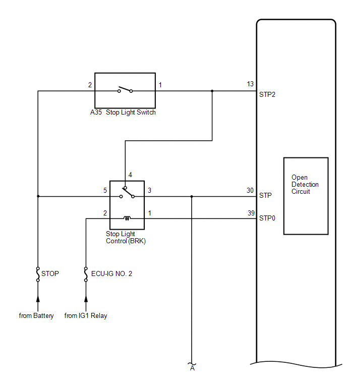
The skid control ECU (housed in the actuator assembly) inputs the stop light switch signal and the condition of brake operation.
The skid control ECU has an open detection circuit, which outputs this DTC when detecting an open in the stop light input line or the ground line of the stop light circuit with the stop light switch off (brake pedal not depressed).
|
DTC Code |
DTC Detection Condition |
Trouble Area |
|---|---|---|
|
C1249/49 |
After the ignition switch is turned to ON, the STP terminal voltage of the ECU is 40% to 67% of its supplied voltage for 3 seconds. |
|
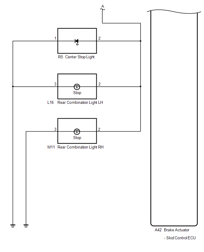
WIRING DIAGRAM
PROCEDURE
|
1. |
CHECK STOP LIGHT OPERATION |
(a) Check that the stop lights come on when the brake pedal is depressed, and go off when the brake pedal is released.
OK:
|
Condition |
Illumination Condition |
|---|---|
|
Brake pedal depressed |
ON |
|
Brake pedal released |
OFF |
| NG | .gif) |
GO TO STEP 4 |
|
.gif)
|
2. |
READ VALUE USING TECHSTREAM (STOP LIGHT SWITCH) |
(a) Connect the Techstream to the DLC3.
(b) Turn the ignition switch to ON.
(c) Select the Data List on the Techstream (See page
.gif) ).
).
ABS/VSC/TRAC
|
Tester Display |
Measurement Item/Range |
Normal Condition |
Diagnostic Note |
|---|---|---|---|
|
Stop Light SW |
Stop light switch / ON or OFF |
ON: Brake pedal depressed OFF: Brake pedal released |
- |
(d) Check that the stop light switch display observed on the Techstream changes according to brake pedal operation.
OK:
The Techstream displays ON or OFF according to brake pedal operation.
| NG | |
GO TO STEP 11 |
|
|
3. |
RECONFIRM DTC |
(a) Turn the ignition switch off.
(b) Clear the DTCs (See page ).
(c) Start the engine.
(d) Depress the brake pedal several times to test the stop light circuit.
(e) Check if the same DTC is recorded (See page
).
|
Result |
Proceed to |
|---|---|
|
DTC (C1249/49) is not output |
A |
|
DTC (C1249/49) is output |
B |
HINT:
If troubleshooting has been carried out according to Problem Symptoms Table,
refer back to the table and proceed to the next step (See page
).
| A | |
CHECK FOR INTERMITTENT PROBLEMS |
| B | |
REPLACE BRAKE ACTUATOR ASSEMBLY |
|
4. |
INSPECT STOP FUSE |
|
(a) Remove the STOP fuse from the main body ECU (driver side junction block). |
|
(b) Measure the resistance according to the value(s) in the table below.
Standard Resistance:
|
Tester Connection |
Condition |
Specified Condition |
|---|---|---|
|
STOP (10 A) fuse |
Always |
Below 1 Ω |
|
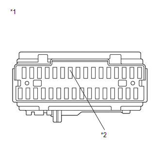
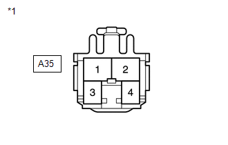
*1 |
Main Body ECU (Driver Side Junction Block) |
|
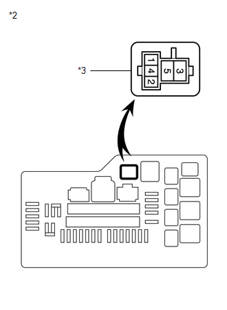
*2 |
STOP Fuse |
| NG | |
REPLACE STOP FUSE |
|
|
5. |
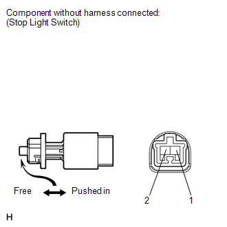
INSPECT STOP LIGHT SWITCH (POWER SOURCE TERMINAL) |
|
(a) Install the STOP fuse. |
|
(b) Make sure that there is no looseness at the locking part and the connecting part of the connector.
(c) Disconnect the stop light switch connector.
(d) Measure the voltage according to the value(s) in the table below.
Standard Voltage:
|
Tester Connection |
Condition |
Specified Condition |
|---|---|---|
|
A35-2 - Body ground |
Always |
11 to 14 V |
|
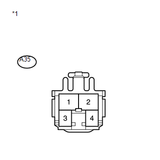
*1 |
Front view of wire harness connector (to Stop Light Switch) |
| NG | |
REPAIR OR REPLACE HARNESS OR CONNECTOR (POWER SOURCE CIRCUIT) |
|
|
6. |
INSPECT STOP LIGHT SWITCH |
|
(a) Measure the resistance according to the value(s) in the table below. Standard Resistance:
|
|
| NG | |
REPLACE STOP LIGHT SWITCH |
|
|
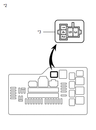
7. |
INSPECT STOP LIGHT CONTROL (BRK) RELAY |
|
(a) Remove the stop light control (BRK) relay. |
|
.png)
(b) Measure the resistance according to the value(s) in the table below.
Standard Resistance:
|
Tester Connection |
Condition |
Specified Condition |
|---|---|---|
|
3 - 4 |
Voltage is not applied between terminals 1 and 2 |
Below 1 Ω |
|
*1 |
Stop Light Control (BRK) Relay |
| NG | |
REPLACE STOP LIGHT CONTROL (BRK) RELAY |
|
|
8. |
CHECK HARNESS AND CONNECTOR (STOP LIGHT SWITCH - ENGINE ROOM RELAY BLOCK) |
(a) Measure the resistance according to the value(s) in the table below.
Standard Resistance:
|
Tester Connection |
Condition |
Specified Condition |
|---|---|---|
|
A35-1 - Stop light control (BRK) relay terminal 4 |
Always |
Below 1 Ω |
|
*1 |
Front view of wire harness connector (to Stop Light Switch) |
|
*2 |
Engine Room Relay Block |
|
*3 |
Stop Light Control (BRK) Relay |
| NG | |
REPAIR OR REPLACE HARNESS OR CONNECTOR |
|
|
9. |
CHECK HARNESS AND CONNECTOR (SKID CONTROL ECU - ENGINE ROOM RELAY BLOCK) |
(a) Make sure that there is no looseness at the locking part and the connecting part of the connector.
(b) Disconnect the skid control ECU connector.
(c) Measure the resistance according to the value(s) in the table below.
Standard Resistance:
|
Tester Connection |
Condition |
Specified Condition |
|---|---|---|
|
A42-30 (STP) - Stop light control (BRK) relay terminal 3 |
Always |
Below 1 Ω |
|
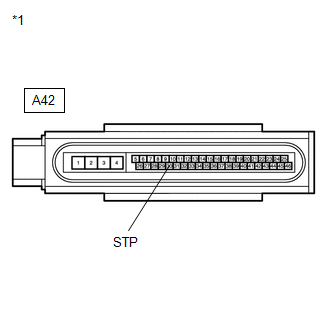
*1 |
Front view of wire harness connector (to Brake Actuator (Skid Control ECU)) |
|
*2 |
Engine Room Relay Block |
|
*3 |
Stop Light Control (BRK) Relay |
| NG | |
REPAIR OR REPLACE HARNESS OR CONNECTOR |
|
|
10. |
RECONFIRM DTC |
(a) Clear the DTCs (See page ).
(b) Start the engine.
(c) Depress the brake pedal several times to test the stop light circuit.
(d) Check if the same DTC is recorded (See page
).
HINT:
Reinstall the relay, connectors, etc. and restore the vehicle to its prior condition before rechecking for DTCs.
|
Result |
Proceed to |
|---|---|
|
DTC (C1249/49) is not output |
A |
|
DTC (C1249/49) is output |
B |
HINT:
If troubleshooting has been carried out according to Problem Symptoms Table,
refer back to the table and proceed to the next step (See page
).
| A | |
INSPECT LIGHTING SYSTEM (STOP LIGHT CIRCUIT) |
| B | |
REPLACE BRAKE ACTUATOR ASSEMBLY |
|
11. |
CHECK HARNESS AND CONNECTOR (SKID CONTROL ECU - ENGINE ROOM RELAY BLOCK) |
(a) Turn the ignition switch off.
(b) Remove the stop light control (BRK) relay.
(c) Make sure that there is no looseness at the locking part and the connecting part of the connector.
(d) Disconnect the skid control ECU connector.
(e) Measure the resistance according to the value(s) in the table below.
Standard Resistance:
|
Tester Connection |
Condition |
Specified Condition |
|---|---|---|
|
A42-30 (STP) - Stop light control (BRK) relay terminal 3 |
Always |
Below 1 Ω |
|
*1 |
Front view of wire harness connector (to Brake Actuator (Skid Control ECU)) |
|
*2 |
Engine Room Relay Block |
|
*3 |
Stop Light Control (BRK) Relay |
| OK | |
REPLACE BRAKE ACTUATOR ASSEMBLY |
| NG | |
REPAIR OR REPLACE HARNESS OR CONNECTOR |
 ECU Version Miss Match (C1288/88)
DESCRIPTION
DTC Code
DTC Detection Condition
Trouble Area
C1288/88
ECM does not match.
ECM
PROCEDURE
1.
...
 Master Cylinder Pressure Sensor Malfunction (C1246/46,C1281/81)
DESCRIPTION
Master cylinder pressure sensor is connected to the skid control ECU in the brake
actuator assembly.
DTC C1281/81 will be cleared when the master cylinder pressure sensor sends a
mas ...
Other materials about Toyota Venza:
Diagnosis System
DIAGNOSIS SYSTEM
1. DESCRIPTION
(a) Air conditioning system data and the Diagnostic Trouble Codes (DTCs) can
be read through the Data Link Connector 3 (DLC3) of the vehicle. When the system
seems to be malfunctioning, use the Techstream to check for malf ...
Low Power Supply Voltage (C1241/94)
DESCRIPTION
If a malfunction in the power source circuit occurs, or a malfunction in communication
with the skid control ECU or in a speed sensor occurs, the AWD control ECU will
prohibit operations by the fail-safe function.
DTC No.
...
How To Proceed With Troubleshooting
CAUTION / NOTICE / HINT
HINT:
Use the following procedure to troubleshoot.
*: Use the Techstream.
PROCEDURE
1.
VEHICLE BROUGHT TO WORKSHOP
NEXT
...

0.1448