Toyota Venza: Power Source Control ECU Malfunction (B2782)
DESCRIPTION
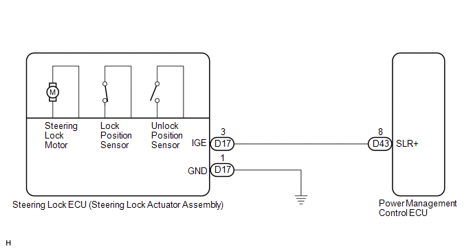
The power management control ECU controls the power supply to activate the steering lock motor. This prevents the steering wheel from being locked while the vehicle is moving.
|
DTC No. |
DTC Detecting Condition |
Trouble Area |
|---|---|---|
|
B2782 |
Steering lock motor drive control circuit is defective. |
|
WIRING DIAGRAM
CAUTION / NOTICE / HINT
HINT:
After replacing the steering lock ECU (steering lock actuator assembly), confirm
the Initialization of the steering lock (See page
.gif) ).
).
PROCEDURE
|
1. |
INSPECT STEERING LOCK ECU (STEERING LOCK ACTUATOR ASSEMBLY) |
|
(a) Measure the voltage according to the value(s) in the table below. Standard Voltage:
HINT: The steering lock ECU and steering lock actuator assembly are supplied as a single unit. |
|
|
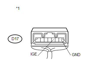
*1 |
Component with harness connected (Steering Lock ECU (Steering Lock Actuator Assembly)) |
| OK | .gif) |
REPLACE STEERING LOCK ECU (STEERING LOCK ACTUATOR ASSEMBLY) |
|
.gif)
|
2. |
CHECK HARNESS AND CONNECTOR (STEERING LOCK ECU - BODY GROUND) |
|
(a) Disconnect the D17 connector from the steering lock actuator assembly. |
|
.png)
(b) Measure the resistance according to the value(s) in the table below.
Standard Resistance:
|
Tester Connection |
Condition |
Specified Condition |
|---|---|---|
|
D17-1 (GND) - Body ground |
Always |
Below 1 Ω |
|
*1 |
Front view of wire harness connector (to Steering Lock ECU (Steering Lock Actuator Assembly)) |
| NG | |
REPAIR OR REPLACE HARNESS OR CONNECTOR |
|
|
3. |
CHECK HARNESS AND CONNECTOR (STEERING LOCK ECU - POWER MANAGEMENT CONTROL ECU) |
|
(a) Disconnect the D43 connector from the power management control ECU. |
|
(b) Measure the resistance according to the value(s) in the table below.
Standard Resistance:
|
Tester Connection |
Condition |
Specified Condition |
|---|---|---|
|
D17-3 (IGE) - D43-8 (SLR+) |
Always |
Below 1 Ω |
|
D17-3 (IGE) - Body ground |
Always |
10 kΩ or higher |
|
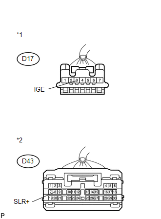
*1 |
Front view of wire harness connector (to Steering Lock ECU (Steering Lock Actuator Assembly)) |
|
*2 |
Front view of wire harness connector (to Power Management Control ECU) |
| OK | |
REPLACE POWER MANAGEMENT CONTROL ECU |
| NG | |
REPAIR OR REPLACE HARNESS OR CONNECTOR |
 Diagnostic Trouble Code Chart
DIAGNOSTIC TROUBLE CODE CHART
If a trouble code is displayed during the DTC check, check the parts listed for
that code in the table below and proceed to the appropriate page.
HINT:
The steering ...
 Open / Short in Steering Lock ECU (B2781)
DESCRIPTION
If the steering lock ECU (steering lock actuator assembly) determines that there
is a malfunction inside the ECU, it outputs this DTC. Diagnostic communication between
the steering lo ...
Other materials about Toyota Venza:
Removal
REMOVAL
CAUTION / NOTICE / HINT
HINT:
Use the same procedure for the LH side and RH side.
The following procedure listed is for the LH side.
PROCEDURE
1. REMOVE REAR WHEEL
2. DRAIN BRAKE FLUID
NOTICE:
If brake fluid leaks onto any pai ...
Transmitter ID1 Operation Stop (C2111/11-C2114/14)
DESCRIPTION
The tire pressure warning valve and transmitter installed in each tire and wheel
assembly measures the tire pressures. The measured values are transmitted as radio
waves to the tire pressure warning antenna and receiver on the body and then se ...
Window Glass Antenna Wire
On-vehicle Inspection
ON-VEHICLE INSPECTION
PROCEDURE
1. INSPECT WINDOW GLASS ANTENNA WIRE
(a) Check for continuity of the antenna.
HINT:
Check for continuity at the center of each antenna wire as shown in the
illustration.
N ...

0.1205