Toyota Venza: Parts Location
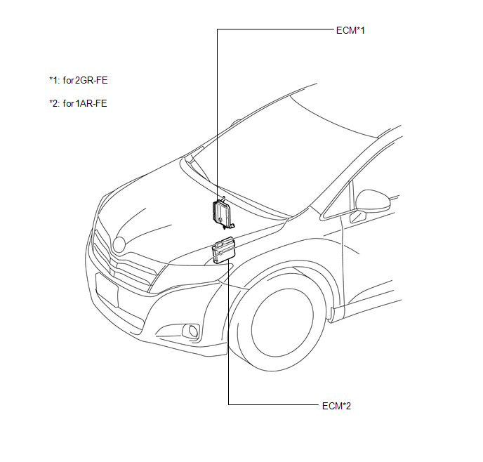
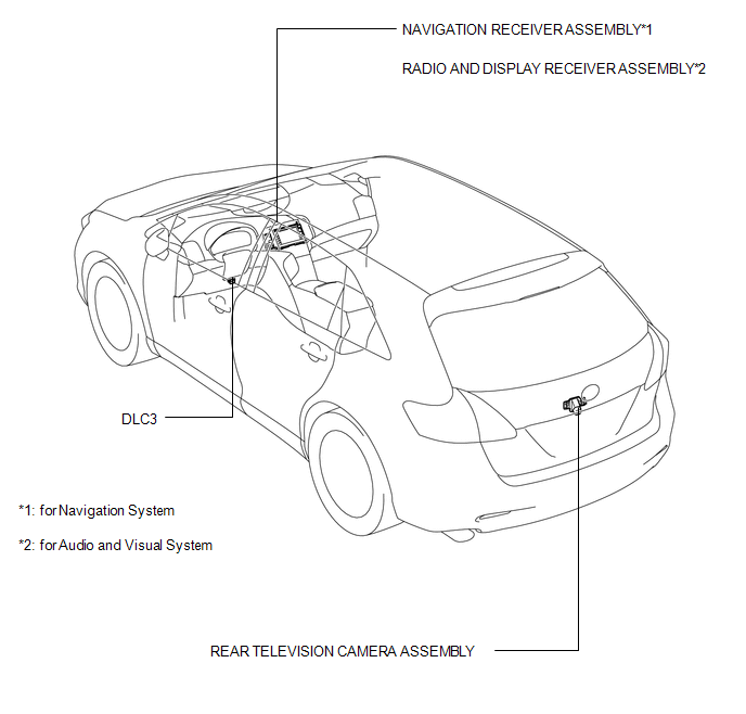
PARTS LOCATION
ILLUSTRATION
ILLUSTRATION
 Precaution
PRECAUTION
1. PRECAUTION FOR DISCONNECTING CABLE FROM NEGATIVE BATTERY TERMINAL
NOTICE:
When disconnecting the cable from the negative (-) battery terminal, initialize
the following systems after ...
 System Diagram
SYSTEM DIAGRAM
Communication Table
Sender
Receiver
Signal
Line
ECM
Navigation Receiver Assembly*1
Radio and ...
Other materials about Toyota Venza:
Precaution
PRECAUTION
1. PRECAUTION FOR DISCONNECTING CABLE FROM NEGATIVE BATTERY TERMINAL
NOTICE:
After the ignition switch is turned off, the navigation receiver assembly
records various types of memory and settings. As a result, after turning
the ig ...
Intermediate Shaft Speed Sensor "A" Circuit (P0791,P0793)
DESCRIPTION
This sensor detects the rotation speed of the counter gear which shows the output
speed of transaxle. By comparing the input turbine speed signal (NT) with the counter
gear speed sensor signal (NC), the TCM detects the shift timing of the gear ...
On-vehicle Inspection
ON-VEHICLE INSPECTION
PROCEDURE
1. CHECK FOR FUEL PUMP OPERATION AND INSPECT FOR FUEL LEAK
(a) Check fuel pump operation.
(1) Connect the Techstream to the DLC3.
(2) Turn the ignition switch to ON and turn the Techstream on.
NOTICE:
Do not start the eng ...

0.1301