Toyota Venza: Parts Location
PARTS LOCATION
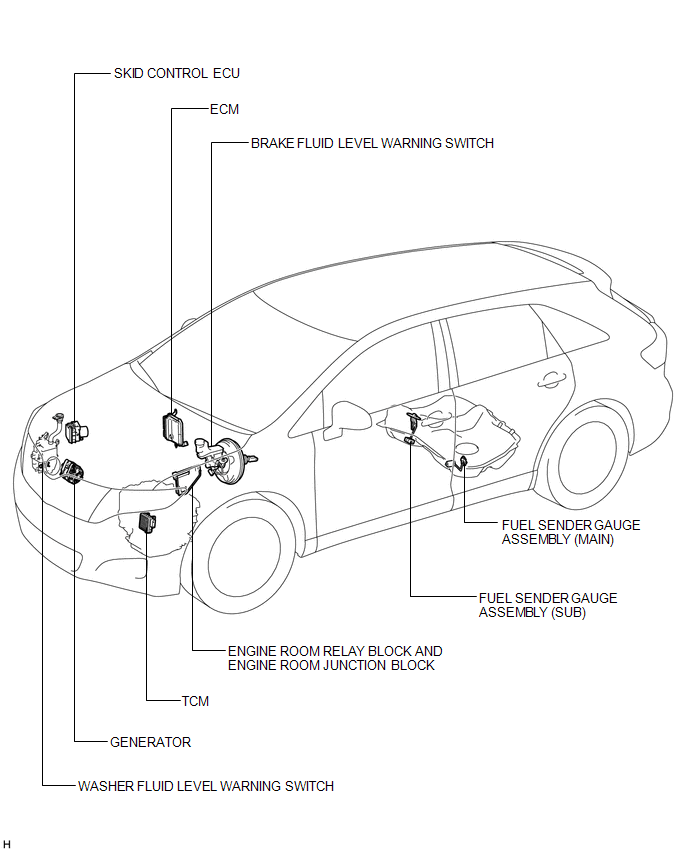
ILLUSTRATION
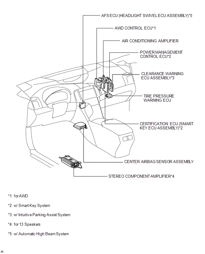
ILLUSTRATION

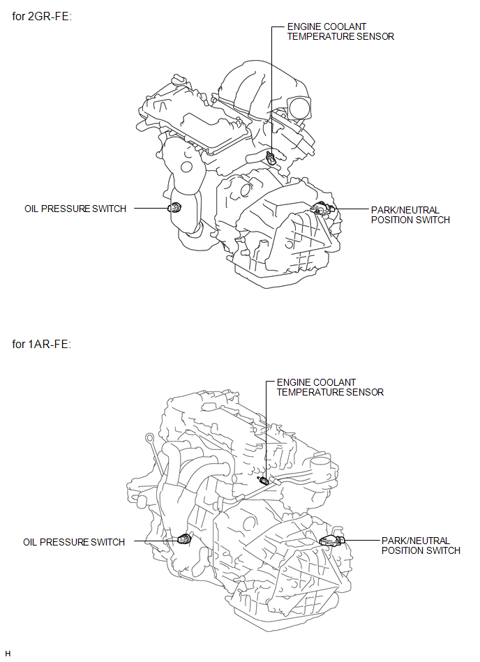
ILLUSTRATION
ILLUSTRATION

 Precaution
PRECAUTION
NOTICE:
When disconnecting the cable from the negative (-) battery terminal, initialize
the following systems after the cable is reconnected.
System Name
See Proc ...
Other materials about Toyota Venza:
Installation
INSTALLATION
PROCEDURE
1. INSTALL ENGINE SWITCH
(a) Attach the 2 claws to install the engine switch.
2. INSTALL LOWER INSTRUMENT PANEL FINISH PANEL ASSEMBLY
(a) Connect the connector.
...
Diagnostic Trouble Code Chart
DIAGNOSTIC TROUBLE CODE CHART
HINT:
If a trouble code is output during the DTC check, inspect the trouble areas listed
for that code. For details of the code, refer to "See page" in the DTC chart.
Inspect the fuses and relays before troub ...
Back Door Closer Operation Malfunction (B2250)
DESCRIPTION
The power back door ECU (power back door motor unit)*1 or back door closer ECU
(multiplex network door ECU)*2 receives signals from the latch switch, sector switch
and back door courtesy switch, which are built into the back door lock. Based o ...

0.1367