Toyota Venza: Parts Location
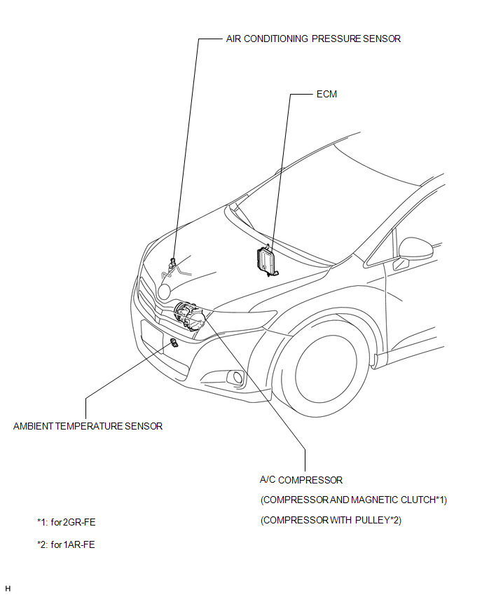
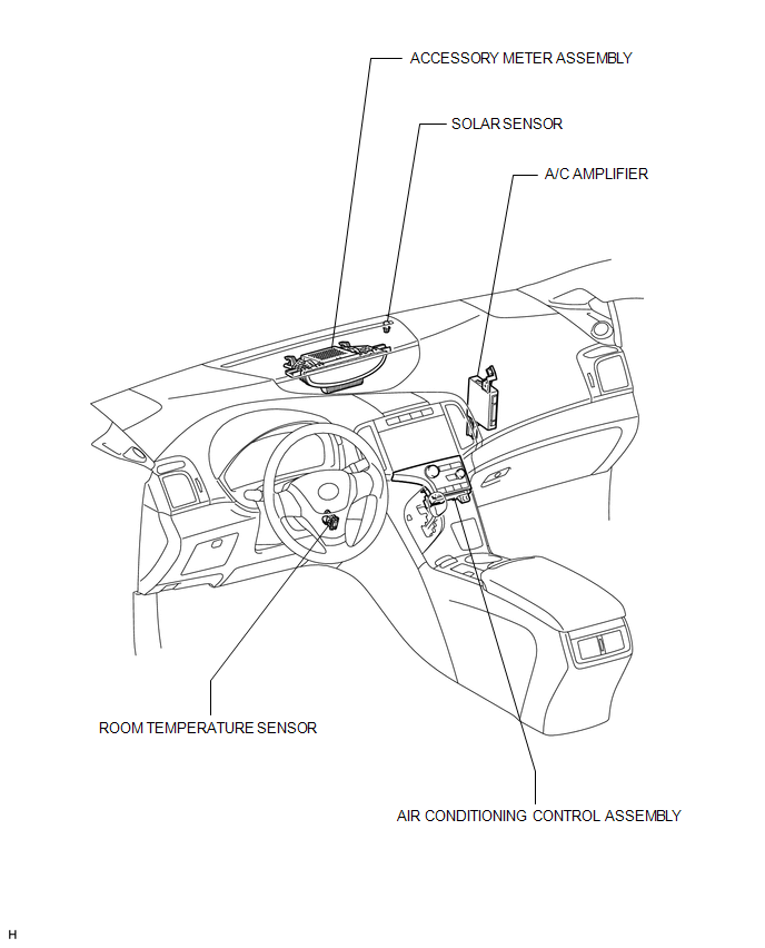
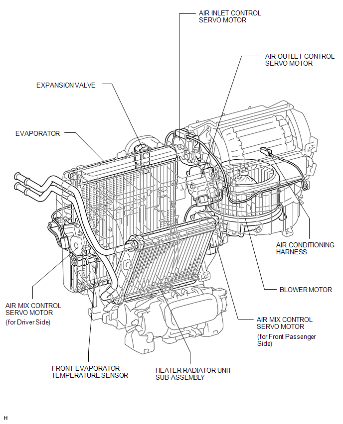
PARTS LOCATION
ILLUSTRATION
ILLUSTRATION
ILLUSTRATION
 Precaution
PRECAUTION
NOTICE:
When disconnecting the cable from the negative (-) battery terminal, initialize
the following systems after the cable is reconnected.
System Name
See Proc ...
 System Diagram
SYSTEM DIAGRAM
Communication Table
Sender
Receiver
Signal
Communication Line
A/C amplifier
ECM
Magnetic clutch req ...
Other materials about Toyota Venza:
Canceling the power back door system (vehicles with power back door)
Turn the main switch to disable the power back door system.
1. Inoperative
2. Operative
The back door cannot be operated even with the wireless remote control or power
back door switch.
A buzzer will sound twice if the power back door switch is pressed ...
Disassembly
DISASSEMBLY
CAUTION / NOTICE / HINT
HINT:
Use an overhaul stand as necessary.
PROCEDURE
1. REMOVE REAR DIFFERENTIAL FILLER PLUG
(a) Remove the rear differential filler plug and gasket.
2. INSPECT ...
Replacement
REPLACEMENT
PROCEDURE
1. REPLACE GENERATOR DRIVE END FRAME BEARING
(a) Remove the 4 screws and bearing retainer from the drive end frame.
(b) Using SST and a hammer, tap out the drive end ...

0.1639