Toyota Venza: Parts Location
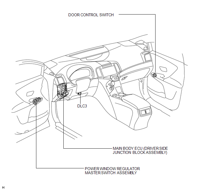
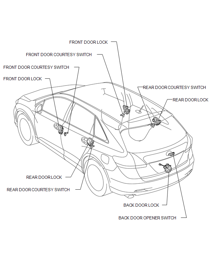
PARTS LOCATION
ILLUSTRATION
ILLUSTRATION
 Precaution
PRECAUTION
NOTICE:
When disconnecting the cable from the negative (-) battery terminal, initialize
the following systems after the cable is reconnected.
System Name
See Proc ...
 System Diagram
SYSTEM DIAGRAM
...
Other materials about Toyota Venza:
Inspection
INSPECTION
PROCEDURE
1. INSPECT FRONT SEAT FRAME WITH ADJUSTER LH
(a) Check operation of the seat frame (slide motor).
(1) w/ Memory:
Check if the seat frame moves smoothly when the battery is connected
to the slide motor connector termin ...
How To Proceed With Troubleshooting
CAUTION / NOTICE / HINT
HINT:
Use the following procedure to troubleshoot the intuitive parking assist
system.
*: Use the Techstream.
PROCEDURE
1.
VEHICLE BROUGHT TO WORKSHOP
NEXT ...
How To Proceed With Troubleshooting
CAUTION / NOTICE / HINT
HINT:
Use the following procedure listed to troubleshoot the Active Torque
Control 4WD system.
*: Use the Techstream.
PROCEDURE
1.
VEHICLE BROUGHT TO WORKSHOP
...

0.1311