Toyota Venza: System Diagram
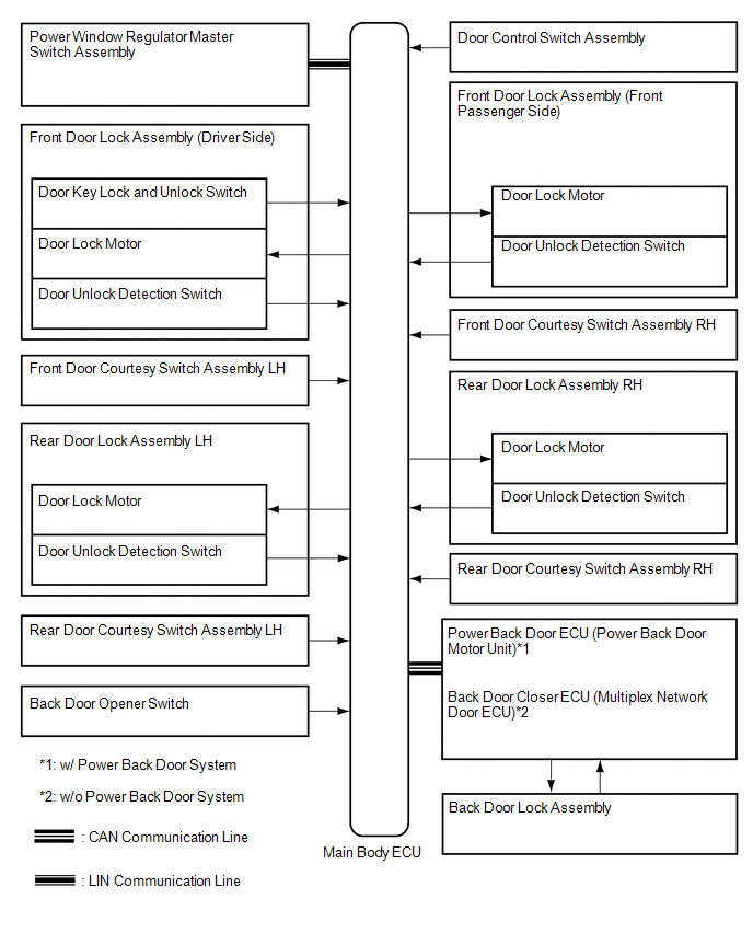
SYSTEM DIAGRAM
 Parts Location
PARTS LOCATION
ILLUSTRATION
ILLUSTRATION
...
 System Description
SYSTEM DESCRIPTION
1. POWER DOOR LOCK CONTROL SYSTEM DESCRIPTION
(a) The power door lock system locks/unlocks all doors.
The door control switch sends "lock/unlock" request signals to the ...
Other materials about Toyota Venza:
Back Door Opener Switch
Components
COMPONENTS
ILLUSTRATION
Removal
REMOVAL
PROCEDURE
1. REMOVE BACK DOOR PANEL TRIM ASSEMBLY
2. REMOVE REAR LIGHT ASSEMBLY LH
3. REMOVE REAR LIGHT ASSEMBLY RH
HINT:
Use the same procedure for the RH side and LH side.
4. REMOVE BA ...
Diagnostic Trouble Code Chart
DIAGNOSTIC TROUBLE CODE CHART
Power Window Control System
DTC Code
Detection Item
Trouble Area
See page
B2311
Power Window Motor Malfunction
1. Battery disconnected when ignit ...
Automatic High Beam
The Automatic High Beam uses an in-vehicle camera sensor to assess the brightness
of streetlights, the lights of oncoming and preceding vehicles, etc., and automatically
turns high beam on or off as necessary.
- Activating the Automatic High Beam sy ...

0.1219