Toyota Venza: Parts Location
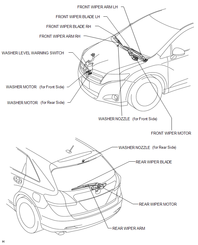
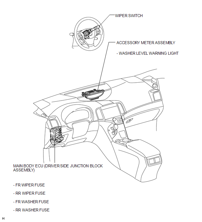
PARTS LOCATION
ILLUSTRATION
ILLUSTRATION
 How To Proceed With Troubleshooting
CAUTION / NOTICE / HINT
HINT:
Use the following procedure to troubleshoot the wiper and washer system.
PROCEDURE
1.
VEHICLE BROUGHT TO WORKSHOP
...
 Problem Symptoms Table
PROBLEM SYMPTOMS TABLE
HINT:
Use the table below to help determine the cause of problem symptoms. If multiple
suspected areas are listed, the potential causes of the symptoms are listed in order
...
Other materials about Toyota Venza:
Back Door Courtesy Switch
Components
COMPONENTS
ILLUSTRATION
Removal
REMOVAL
PROCEDURE
1. REMOVE BACK DOOR PANEL TRIM ASSEMBLY
2. REMOVE BACK DOOR LOCK ASSEMBLY
(a) Disconnect the connector.
(b) Disengage the c ...
Indicator Circuit
DESCRIPTION
The headlight beam level control system indicator light in the combination meter
assembly comes on for approximately 3 seconds when the ignition switch is turned
to ON. The indicator light also comes on when the headlight leveling ECU assembly ...
CD cannot be Inserted or is Ejected Right After Insertion
PROCEDURE
1.
CHECK IF A PROPER CD IS INSERTED
(a) Make sure that the CD is an audio CD or a CD with an MP3, WMA or AAC files,
and that it is not deformed, flawed, stained, deteriorated or otherwise defective.
OK:
Normal C ...

0.1439