Toyota Venza: Engine Hood Courtesy Switch
Components
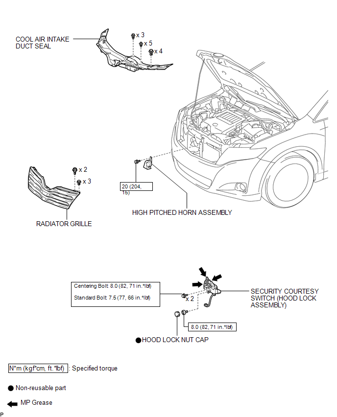
COMPONENTS
ILLUSTRATION
Inspection
INSPECTION
PROCEDURE
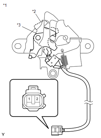
1. INSPECT SECURITY COURTESY SWITCH (HOOD LOCK ASSEMBLY)
|
(a) Measure the resistance according to the value(s) in the table below. Standard Resistance:
If the result is not as specified, replace the security courtesy switch (hood lock assembly). |
|
Removal
REMOVAL
PROCEDURE
1. REMOVE COOL AIR INTAKE DUCT SEAL
.gif)
2. REMOVE RADIATOR GRILLE
3. REMOVE HIGH PITCHED HORN ASSEMBLY
4. REMOVE SECURITY COURTESY SWITCH (HOOD LOCK ASSEMBLY)
Installation
INSTALLATION
PROCEDURE
1. INSTALL SECURITY COURTESY SWITCH (HOOD LOCK ASSEMBLY)
.gif)
2. INSTALL HIGH PITCHED HORN ASSEMBLY
3. INSTALL RADIATOR GRILLE
4. INSTALL COOL AIR INTAKE DUCT SEAL
5. INSPECT HOOD SUB-ASSEMBLY
6. ADJUST HOOD SUB-ASSEMBLY
 Electrical Key Oscillator(for Rear Side)
Components
COMPONENTS
ILLUSTRATION
Removal
REMOVAL
PROCEDURE
1. REMOVE REAR BUMPER PLATE LH
2. REMOVE REAR BUMPER PLATE RH
3. REMOVE REAR BUMPER ASSEMBLY
4. REMOVE ELECTRICAL K ...

Other materials about Toyota Venza:
Pressure Control Solenoid "B" Electrical (Shift Solenoid Valve SL2) (P0778)
DESCRIPTION
Changing from 1st to 6th is performed by the TCM turning shift solenoid valves
SL1, SL2, SL3, SL4 and SL on and off. If an open or short circuit occurs in any
of the shift solenoid valves, the TCM controls the remaining normal shift solenoid
...
Door Courtesy Switch Circuit
DESCRIPTION
The main body ECU (driver side junction block assembly) detects the condition
of the door courtesy light switch.
WIRING DIAGRAM
PROCEDURE
1.
READ VALUE USING TECHSTREAM
(a) Connect the Techstream to the DLC3 ...
Installation
INSTALLATION
PROCEDURE
1. INSTALL FRONT DOOR BELT MOULDING
(a) Engage the 5 claws to install the front door belt moulding.
(b) Install the clip.
2. INSTALL FRONT DOOR GLASS RUN
3. INSTALL FRONT ...

0.1609