Toyota Venza: Rear Center Seat Inner Belt Assembly
Components
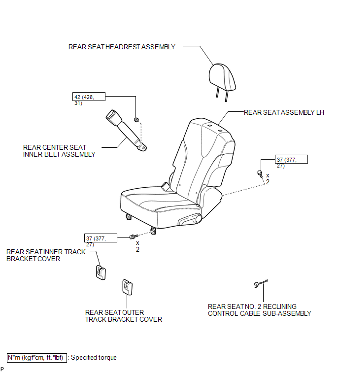
COMPONENTS
ILLUSTRATION
Removal
REMOVAL
PROCEDURE
1. REMOVE REAR SEAT HEADREST ASSEMBLY
.gif)
2. REMOVE REAR SEAT INNER TRACK BRACKET COVER
3. REMOVE REAR SEAT OUTER TRACK BRACKET COVER
4. DISCONNECT REAR SEAT NO. 2 RECLINING CONTROL CABLE SUB-ASSEMBLY
5. REMOVE REAR SEAT ASSEMBLY LH
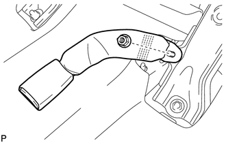
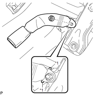
6. REMOVE REAR CENTER SEAT INNER BELT ASSEMBLY
|
(a) Remove the nut and the rear center seat inner belt assembly. |
|
Installation
INSTALLATION
PROCEDURE
1. INSTALL REAR CENTER SEAT INNER BELT ASSEMBLY
|
(a) Install the rear center seat inner belt assembly with the nut. Text in Illustration
Torque: 42 N·m {428 kgf·cm, 31 ft·lbf} NOTICE: Do not allow the anchor part of the rear seat outer belt assembly to overlap the protruding part of the floor panel. |
|
2. INSTALL REAR SEAT ASSEMBLY LH
.gif)
3. CONNECT REAR SEAT NO. 2 RECLINING CONTROL CABLE SUB-ASSEMBLY
4. INSTALL REAR SEAT INNER TRACK BRACKET COVER
5. INSTALL REAR SEAT OUTER TRACK BRACKET COVER
6. INSTALL REAR SEAT HEADREST ASSEMBLY
 Disposal
DISPOSAL
CAUTION / NOTICE / HINT
CAUTION:
Before performing pre-disposal deployment of any SRS component, review and closely
follow all applicable environmental and hazardous material regulations ...

Other materials about Toyota Venza:
Freeze Frame Data
FREEZE FRAME DATA
1. DESCRIPTION
The ECM records vehicle and driving condition information as freeze
frame data the moment a DTC is stored. When troubleshooting, freeze frame
data can be helpful in determining whether the vehicle was moving or ...
Data List / Active Test
DATA LIST / ACTIVE TEST
1. DATA LIST
HINT:
Using the Techstream to read the Data List allows the values or states of switches,
sensors, actuators and other items to be read without removing any parts. This non-intrusive
inspection can be very useful bec ...
Components
COMPONENTS
ILLUSTRATION
ILLUSTRATION
ILLUSTRATION
ILLUSTRATION
ILLUSTRATION
ILLUSTRATION
...

0.1162