Toyota Venza: Parts Location
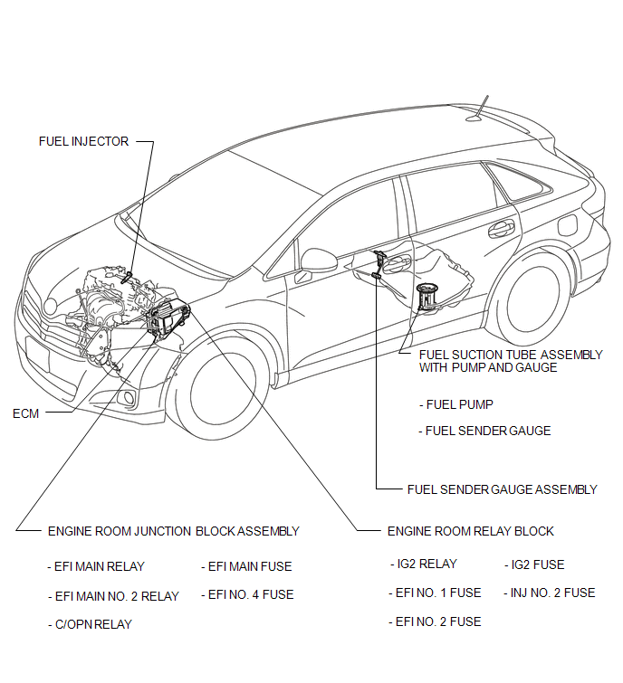
PARTS LOCATION
ILLUSTRATION
 Precaution
PRECAUTION
1. BEFORE WORKING ON FUEL SYSTEM
(a) When disconnecting a fuel line, fuel will splash. So observe the following
precautions:
(1) Do not smoke or work near fire when handling the fuel s ...
 On-vehicle Inspection
ON-VEHICLE INSPECTION
PROCEDURE
1. CHECK FOR FUEL PUMP OPERATION AND INSPECT FOR FUEL LEAK
(a) Check fuel pump operation.
(1) Connect the Techstream to the DLC3.
(2) Turn the ignition switch to O ...
Other materials about Toyota Venza:
Diagnostic Trouble Code Chart
DIAGNOSTIC TROUBLE CODE CHART
Rear View Monitor System
DTC Code
Detection Item
See page
C1622
Back Camera Disconnected
...
Air Conditioning Compressor Magnetic Clutch Circuit
DESCRIPTION
When the A/C amplifier is turned on, a magnetic clutch ON signal is sent from
the MGC terminal of the A/C amplifier. Then, the MGC relay turns on to operate the
magnetic clutch.
WIRING DIAGRAM
CAUTION / NOTICE / HINT
NOTICE:
Inspect the ...
MIL Circuit
DESCRIPTION
The MIL (Malfunction Indicator Lamp) is used to indicate vehicle malfunctions
detected by the ECM. By turning the ignition switch to ON, power is supplied to
the MIL circuit, and the ECM provides the circuit ground which illuminates the MIL.
...

0.1479