Toyota Venza: Parking Brake Switch Circuit
DESCRIPTION
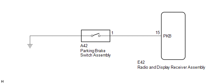
This circuit is from the parking brake switch assembly to the radio and display receiver assembly.
WIRING DIAGRAM
PROCEDURE
|
1. |
CHECK BRAKE WARNING LIGHT |
(a) Check that the brake warning light comes on when the parking brake is applied and goes off when it is released.
OK:
The brake warning light operates as specified above.
| NG | .gif) |
GO TO BRAKE CONTROL / DYNAMIC CONTROL SYSTEMS |
|
.gif)
|
2. |
CHECK HARNESS AND CONNECTOR (PARKING BRAKE SWITCH ASSEMBLY - RADIO AND DISPLAY RECEIVER ASSEMBLY) |
(a) Disconnect the E42 radio and display receiver assembly connector.
(b) Disconnect the A42 parking brake switch assembly connector.
(c) Measure the resistance according to the value(s) in the table below.
Standard Resistance:
|
Tester Connection |
Condition |
Specified Condition |
|---|---|---|
|
E42-15 (PKB) - A42-1 |
Always |
Below 1 Ω |
|
E42-15 (PKB) - Body ground |
Always |
10 kΩ or higher |
| OK | |
PROCEED TO NEXT SUSPECTED AREA SHOWN IN PROBLEM SYMPTOMS TABLE |
| NG | |
REPAIR OR REPLACE HARNESS OR CONNECTOR |
 Illumination Circuit
DESCRIPTION
Power is supplied to the radio and display receiver assembly and steering pad
switch assembly illumination when the light control switch is in the tail or head
position.
WIRING DIAGR ...
 Speaker Circuit
DESCRIPTION
If there is a short in a speaker circuit, the radio and display receiver
assembly detects it and stops output to the speakers.
Thus sound cannot be heard from the speakers ...
Other materials about Toyota Venza:
Adjustment
ADJUSTMENT
CAUTION / NOTICE / HINT
CAUTION:
Before adjusting the door positions of vehicles equipped with side and curtain
shield airbags, be sure to disconnect the battery. After adjustment, check that
the SRS warning light is operating normally and ...
System Diagram
SYSTEM DIAGRAM
Communication Table
Sender
Receiver
Signal
Line
Main Body ECU
(Driver Side Junction Block Assembly)
Clearance Warning ECU Assembly
Destination information
...
Open in Rear Floor Electrical Key Oscillator Circuit (B27A6)
DESCRIPTION
The certification ECU (smart key ECU assembly) generates a request signal and
sends it to the indoor electrical key oscillator (for center floor). To detect the
key inside the cabin, the indoor electrical key oscillator (for center floor) crea ...

0.1324