Toyota Venza: Transmission Wire(when Using The Engine Support Bridge)
Components
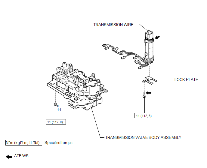
COMPONENTS
ILLUSTRATION
Installation
INSTALLATION
PROCEDURE
1. INSTALL TRANSMISSION WIRE
|
(a) Coat the O-ring with ATF. |
|
.png)
(b) Coat the bolt with ATF.
(c) Install the transmission wire and lock plate to the transmission valve body assembly with the bolt.
Torque:
11 N·m {112 kgf·cm, 8 ft·lbf}
(d) Engage the clamp.
(e) Connect the 8 shift solenoid valve connectors.
(f) Connect the speed sensor connector.
2. INSTALL TRANSMISSION VALVE BODY ASSEMBLY
See page .gif)
Removal
REMOVAL
PROCEDURE
1. REMOVE TRANSMISSION VALVE BODY ASSEMBLY
See page .gif)
2. REMOVE TRANSMISSION WIRE
|
(a) Disconnect the speed sensor connector. |
|
.png)
(b) Disconnect the 8 shift solenoid valve connectors.
(c) Disengage the clamp.
|
(d) Remove the bolt, lock plate and transmission wire from the transmission valve body assembly. |
|
.png)
 Transmission Wire(when Not Using The Engine Support Bridge)
Components
COMPONENTS
ILLUSTRATION
Installation
INSTALLATION
PROCEDURE
1. INSTALL TRANSMISSION WIRE
(a) Coat the O-ring with ATF.
...

Other materials about Toyota Venza:
System Description
SYSTEM DESCRIPTION
1. ILLUMINATED ENTRY SYSTEM
(a) The illuminated entry system has the following control functions:
Control
Outline
Lights that Operate
Actuation Area-linked*2
When a registered k ...
System Description
SYSTEM DESCRIPTION
1. ENGINE IMMOBILISER SYSTEM DESCRIPTION
The engine immobiliser system is designed to prevent the vehicle from being stolen.
This system uses the transponder key ECU assembly that stores the key codes of authorized
ignition keys. If an ...
Removal
REMOVAL
PROCEDURE
1. DISCONNECT CABLE FROM NEGATIVE BATTERY TERMINAL
NOTICE:
When disconnecting the cable, some systems need to be initialized after the cable
is reconnected (See page ).
2. REMOVE FRONT WHEEL RH
3. REMOVE NO. 1 ENGINE UNDER COVER
4. ...

0.156