Toyota Venza: Terminals Of Ecu
TERMINALS OF ECU
1. CHECK POWER MANAGEMENT CONTROL ECU
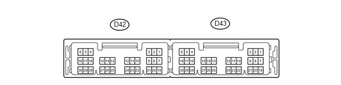
(a) Disconnect the D42 and D43 connectors.
(b) Measure the voltage and resistance according to the value(s) in the table below.
|
Tester Connection |
Wiring Color |
Terminal Description |
Condition |
Specified Condition |
|---|---|---|---|---|
|
D42-2 (STA) - Body ground |
P - Body ground |
Starter relay operation signal |
Always |
93.8 to 136.4 Ω |
|
D42-3 (STAR) - Body ground |
G - Body ground |
Park neutral position switch signal |
Shift lever in P or N |
93.8 to 136.4 Ω |
|
D42-3 (STAR) - Body ground |
G - Body ground |
Park neutral position switch signal |
Shift lever in except P or N |
10 kΩ or higher |
|
D42-8 (IG2D) - Body ground |
GR - Body ground |
IG2 relay operation signal |
Always |
131 to 230 Ω |
|
D42-10 (STP1) - Body ground |
V - Body ground |
Stop light switch signal |
Brake pedal depressed |
11 to 14 V |
|
D42-10 (STP1) - Body ground |
V - Body ground |
Stop light switch signal |
Brake pedal released |
Below 1 V |
|
D43-1 (AM22) - Body ground |
LG - Body ground |
+B power supply |
Always |
11 to 14 V |
|
D43-2 (AM21) - Body ground |
Y - Body ground |
+B power supply |
Always |
11 to 14 V |
|
D43-3 (SLP) - Body ground |
G - Body ground |
Steering lock actuator position signal |
Always |
10 kΩ or higher |
|
D43-5 (GND2) - Body ground |
W-B - Body ground |
Ground |
Always |
Below 1 Ω |
|
D43-6 (GND) - Body ground |
W - Body ground |
Ground |
Engine switch not pushed |
10 kΩ or higher |
|
D43-8 (SLR+) - Body ground |
R - Body ground |
Steering lock motor signal |
Always |
10 kΩ or higher |
|
D43-11 (CA3N) - Body ground |
W - Body ground |
CAN communication line |
Always |
10 kΩ or higher |
|
D43-12 (CA3P) - Body ground |
G - Body ground |
CAN communication line |
Always |
10 kΩ or higher |
|
D43-13 (CA1L) - Body ground |
W - Body ground |
CAN communication line |
Always |
10 kΩ or higher |
|
D43-14 (CA1H) - Body ground |
Y - Body ground |
CAN communication line |
Always |
10 kΩ or higher |
|
D43-17 (SSW2) - Body ground |
V - Body ground |
Engine switch signal |
Engine switch pushed |
Below 1 Ω |
|
D43-17 (SSW2) - Body ground |
V - Body ground |
Engine switch signal |
Engine switch not pushed |
10 kΩ or higher |
|
D43-18 (SSW1) - Body ground |
L - Body ground |
Engine switch signal |
Engine switch pushed |
Below 1 Ω |
|
D43-20 (IG1D) - Body ground |
V - Body ground |
IG1 relay operation signal |
Always |
50.625 to 61.875 Ω |
|
D43-24 (LIN2) - Body ground |
BR - Body ground |
LIN communication line |
Always |
10 kΩ or higher |
If the result is not as specified, there may be a malfunction on the wire harness side.
(c) Reconnect the D42 and D43 connectors.
(d) Measure the voltage and check pulses according to the value(s) in the table below.
|
Tester Connection |
Wiring Color |
Terminal Description |
Condition |
Specified Condition |
|---|---|---|---|---|
|
D42-4 (NE) - D43-6 (GND) |
GR - W |
Crankshaft position sensor signal |
Idling with warm engine |
Pulse generation (See waveform 1) |
|
D42-8 (IG2D) - D43-6 (GND) |
GR - W |
IG2 signal |
Engine switch on (IG) |
Output voltage at terminal AM21 or AM22 is -2 V or more |
|
D42-8 (IG2D) - D43-6 (GND) |
GR - W |
IG2 signal |
Engine switch on (ACC) |
Below 1 V |
|
D43-3 (SLP) - D43-6 (GND) |
G - W |
Steering lock actuator signal |
Steering lock released |
Pulse generation (See waveform 2) |
|
D43-3 (SLP) - D43-6 (GND) |
G - W |
Steering lock actuator signal |
Shift lever in P Steering lock locked |
Pulse generation (See waveform 2) |
|
D43-8 (SLR+) - D43-6 (GND) |
R - W |
Steering motor signal |
Steering lock motor operating |
Below 1 V |
|
D43-8 (SLR+) - D43-6 (GND) |
R - W |
Steering motor signal |
Steering lock motor not operating |
11 to 14 V |
|
D43-2 (INDW) - D43-6 (GND) |
GR - W |
Warning signal |
Brake pedal depressed, shift lever in P, engine switch on (ACC, IG) |
8 to 14 V |
|
D43-16 (P) - D43-6 (GND) |
R - W |
Shift lock signal |
Shift lever in P |
8 to 14 V |
|
D43-16 (P) - D43-6 (GND) |
R - W |
Shift lock signal |
Shift lever not in P |
Below 1 V |
|
D43-17 (SSW2) - D43-6 (GND) |
V - W |
Engine switch signal |
Engine switch not pushed |
Output voltage at terminal AM21 or AM22 is -2 V or more |
|
D43-17 (SSW2) - D43-6 (GND) |
V - W |
Engine switch signal |
Engine switch pushed |
Below 1 V |
|
D43-18 (SSW1) - D43-6 (GND) |
L - W |
Engine switch signal |
Engine switch not pushed |
Output voltage at terminal AM21 or AM22 is -2 V or more |
|
D43-18 (SSW1) - D43-6 (GND) |
L - W |
Engine switch signal |
Engine switch pushed |
Below 1 V |
|
D43-19 (ACCD) - D43-6 (GND) |
G - W |
ACC signal |
Engine switch on (ACC) |
8 to 14 V |
|
D43-19 (ACCD) - D43-6 (GND) |
G - W |
ACC signal |
Engine switch off |
Below 1 V |
|
D43-20 (IG1D) - D43-6 (GND) |
V - W |
IG1 signal |
Engine switch on (IG) |
8 to 14 V |
|
D43-20 (IG1D) - D43-6 (GND) |
V - W |
IG1 signal |
Engine switch on (ACC) |
Below 1 V |
|
D43-22 (INDS) - D43-6 (GND) |
Y - W |
Vehicle condition signal |
Brake pedal depressed, shift lever in P |
8 to 14 V |
|
D43-23 (SUT) - D43-6 (GND) |
L - W |
Vehicle speed signal |
Engine switch on (IG), wheel rotated slowly |
Pulse generation (See waveform 3) |
If the result is not as specified, the ECU may have a malfunction.
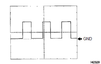
(e) Using an oscilloscope, check the signal waveform of the ECU.
(1) Waveform 1
.png)
|
Tester Connection |
D42-4 (NE) - D43-6 (GND) |
|
Tool Setting |
5 V/DIV., 2 ms./DIV. |
|
Vehicle Condition |
Idling with warm engine |
HINT:
The wavelength becomes shorter as the engine speed increases.
(2) Waveform 2

|
Tester Connection |
D42-3 (SLP) - D43-6 (GND) |
|
Tool Setting |
2 V/DIV., 100 ms./DIV. |
|
Vehicle Condition |
Steering lock/unlock |
(3) Waveform 3
|
Tester Connection |
D43-23 (SUT) - D43-6 (GND) |
|
Tool Setting |
5 V/DIV., 10 ms./DIV. |
|
Vehicle Condition |
Driving at approx. 20 km/h (12 mph) |
HINT:
The wavelength becomes shorter as the vehicle speed increases.
2. CHECK CERTIFICATION ECU (SMART KEY ECU ASSEMBLY)
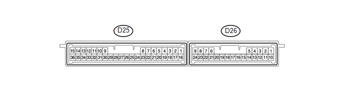
(a) Disconnect the D25 connector.
(b) Measure the voltage and resistance according to the value(s) in the table below.
|
Tester Connection |
Wiring Color |
Terminal Description |
Condition |
Specified Condition |
|---|---|---|---|---|
|
D25-1 (+B) - Body ground |
G - Body ground |
+B power supply |
Always |
11 to 14 V |
|
D25-11 (SWIL) - Body ground |
R - Body ground |
Illumination signal |
Light control switch tail or head |
8 to 14 V |
|
D25-15 (E)- Body ground |
B - Body ground |
Ground |
Always |
Below 1 Ω |
|
D25-16 (IG) - Body ground |
R - Body ground |
IG power supply |
Engine switch on (IG) |
11 to 14 V |
|
D25-29 (LIN) - Body ground |
P - Body ground |
LIN communication line |
Always |
10 kΩ or higher |
If the result is not as specified, there may be a malfunction on the wire harness side.
(c) Reconnect the D25 connector.
(d) Measure the voltage according to the value(s) in the table below.
|
Tester Connection |
Wiring Color |
Terminal Description |
Condition |
Specified Condition |
|---|---|---|---|---|
|
D25-11 (SWIL) - Body ground |
R - Body ground |
Illumination signal |
Light control switch tail or head |
8 to 14 V |
If the result is not as specified, the ECU may have a malfunction.
3. CHECK STEERING LOCK ACTUATOR ASSEMBLY (STEERING LOCK ECU)

(a) Disconnect the D17 ECU connector.
(b) Measure the voltage and resistance according to the value(s) in the table below.
|
Tester Connection |
Wiring Color |
Terminal Description |
Condition |
Specified Condition |
|---|---|---|---|---|
|
D17-1 (GND) - Body ground |
W-B - Body ground |
Ground |
Always |
Below 1 Ω |
|
D17-6 (IG2) - Body ground |
LG - Body ground |
Ignition power supply |
Engine switch on (IG) |
11 to 14 V |
|
D17-6 (IG2) - Body ground |
LG - Body ground |
Ignition power supply |
Engine switch off |
Below 1 V |
|
D17-7 (B) - Body ground |
P - Body ground |
+B power supply |
Always |
11 to 14 V |
- If the result is not as specified, there may be a malfunction on the wire harness side.
(c) Reconnect the D17 ECU connector.
(d) Measure the voltage according to the value(s) in the table below.
|
Tester Connection |
Wiring Color |
Terminal Description |
Condition |
Specified Condition |
|---|---|---|---|---|
|
D17-4 (SLP1) - D17-1 (GND) |
V - W-B |
Steering lock actuator position signal |
Steering locked |
11 to 14 V |
|
D17-4 (SLP1) - D17-1 (GND) |
V - W-B |
Steering lock actuator position signal |
Steering released |
Below 1 V |
- If the result is not as specified, the ECU may have a malfunction.
 Problem Symptoms Table
PROBLEM SYMPTOMS TABLE
HINT:
Use the table below to help determine the cause of problem symptoms. If multiple
suspected areas are listed, the potential causes of the symptoms are listed in order
...
 Diagnosis System
DIAGNOSIS SYSTEM
1. DESCRIPTION
(a) Push-button start function data and the Diagnostic Trouble Codes (DTCs) can
be read through the Data Link Connector 3 (DLC3) of the vehicle. When the function
...
Other materials about Toyota Venza:
Brake Line
Precaution
PRECAUTION
1. TROUBLESHOOTING PRECAUTION
NOTICE:
Since the brake lines are critical safety related parts, be sure to
disassemble and inspect the components if a brake fluid leak is found. If
any abnormality is found, replace th ...
Noise Occurs from Generator while Engine is Running
PROCEDURE
1.
CHECK LOOSENESS OF V-RIBBED BELT
(a) Check the tension of the belt by pushing it down with a finger.
OK:
The tension of the belt is enough.
NG
ADJUST V-RIBBED BELT
...
Diagnostic Trouble Code Chart
DIAGNOSTIC TROUBLE CODE CHART
If a trouble code is displayed during the DTC check, inspect the trouble areas
listed for that code. For details of the code, refer to the ''See page'' below.
Front Power Seat Control System (w/ Memory)
...

0.178