Toyota Venza: Installation
INSTALLATION
PROCEDURE
1. INSTALL CHARCOAL CANISTER LEAK DETECTION PUMP SUB-ASSEMBLY
|
(a) Engage the 2 claws to install a new charcoal canister leak detection pump sub-assembly to the charcoal canister assembly. NOTICE:
|
|
2. INSTALL CHARCOAL CANISTER ASSEMBLY
(a) Connect the 2 clips to install the charcoal canister assembly.
(b) Install the 4 nuts.
Torque:
5.5 N·m {56 kgf·cm, 49 in·lbf}
(c) Connect the air line tube to the charcoal canister leak detection pump sub-assembly.
NOTICE:
- Check that there are no scratches or foreign matter around the connecting parts of the tube connector and pipe before performing this work.
- After connecting the air line tube, check that the air line tube is securely connected by pulling on the tube connector and the charcoal canister.
(d) Connect the purge line hose to the charcoal canister assembly.
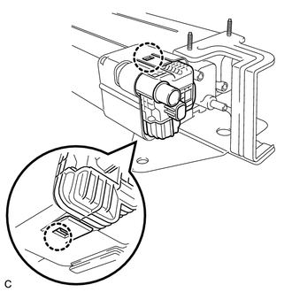
(e) Connect the connector to the charcoal canister leak detection pump sub-assembly.
(f) Push in the tube connector to the pipe and push up the retainer to connect the vent line tube.
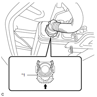 Text in Illustration
|
*1 |
Retainer |
.png) |
Push Up |
NOTICE:
- Check that there are no scratches or foreign matter around the connecting parts of the tube connector and pipe before performing this work.
- After connecting the vent line tube, check that the vent line tube is securely connected by pulling on the tube connector and the charcoal canister.
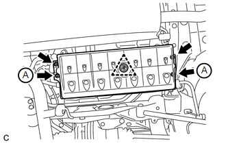
3. INSTALL NO. 1 FLOOR UNDER COVER
|
(a) Install the No. 1 floor under cover with the 4 nuts and clip. Torque: Nut A : 2.2 N·m {22 kgf·cm, 19 in·lbf} HINT: The 4 nuts and clip are attached to the No. 1 floor under cover. |
|
 Inspection
INSPECTION
PROCEDURE
1. INSPECT CHARCOAL CANISTER ASSEMBLY
(a) Visually check the charcoal canister assembly.
(1) Visually check the charcoal canister assembly for cracks or damage.
...
 Emission Control System
Parts Location
PARTS LOCATION
ILLUSTRATION
On-vehicle Inspection
ON-VEHICLE INSPECTION
PROCEDURE
1. INSPECT FUEL CUT-OFF RPM
(a) Increase the engine speed to at least 3500 rpm.
...
Other materials about Toyota Venza:
Removal
REMOVAL
CAUTION / NOTICE / HINT
NOTICE:
If automatic transaxle assembly parts are replaced, refer to Parts Replacement
Compensation Table to determine if any additional operations are necessary (See
page ).
PROCEDURE
1. REMOVE ENGINE ASSEMBLY WITH TR ...
Intake System
Parts Location
PARTS LOCATION
ILLUSTRATION
System Diagram
SYSTEM DIAGRAM
On-vehicle Inspection
ON-VEHICLE INSPECTION
PROCEDURE
1. INSPECT INTAKE SYSTEM
HINT:
Perform "Inspection After Repair" after repairing vacuum leaks in the ...
Fuel Injector Circuit
DESCRIPTION
The fuel injector assemblies are located on the intake manifold. They inject
fuel into the cylinders based on signals from the ECM.
WIRING DIAGRAM
CAUTION / NOTICE / HINT
NOTICE:
Inspect the fuses for circuits related to this system befo ...

0.1566