Toyota Venza: Initialization
INITIALIZATION
1. Inspection After Repair
Perform learning value reset and idle learning after replacing or servicing parts related to engine operation. Details on procedures required are indicated by an asterisk and a number, and are explained in detail following the table.
|
Part Replaced |
Engine Operation |
Learning Value Reset*1 |
Idle Learning*2 |
|---|---|---|---|
|
- |
○ |
○ |
|
Engine assembly |
- |
○ |
○ |
|
Confirm the following: Perform learning value reset and idle learning when one or more of the following conditions is met.
|
○ |
○ |
|
The items in the list above do not apply. |
- |
- |
|
|
Knock control sensor*4 |
- |
- |
- |
- ○: Necessary.
- -: Unnecessary.
NOTICE:
Engine learned values cannot be reset by disconnecting the battery negative (-) terminal or removing the EFI NO. 1 and ETCS fuses.
- *1: Learning Value Reset
- Connect the Techstream to the DLC3.
- Turn the ignition switch to ON.
- Turn the Techstream on.
- Enter the following menus: Powertrain / Engine / Utility / Learning Value Reset.
- Confirm the following conditions as instructed on the screen.
- - Ignition switch ON
- - Engine stopped
- - Battery voltage is higher than 9 V
- After confirming, select "Next" and initialize the learned value.
HINT:
If a message indicating learned value initialization failure is displayed on the screen, confirm the execution conditions, and perform learned value initialization again.
- After the completion of learned value initialization, confirm
the air fuel ratio learned values (A/F Learn Value Idle #1, A/F
Learn Value Low #1, A/F Learn Value Mid1 #1, A/F Learn Value Mid2
#1, and A/F Learn Value High #1) in the Data List.
If 0 is displayed for all the air fuel ratio learned values, initialization has completed correctly.
If a value other than 0 is displayed for one of the air fuel ratio learned values, perform initialization again. After initialization, confirm the air fuel ratio learned values. If a value other than 0 is displayed, replace the ECM.
- *2: Idle Learning
- Turn the ignition switch off and wait for at least 30 seconds.
- Start the engine and warm it up until the engine coolant temperature
is 80°C (176°F) or higher.
HINT:
Learning starts when the engine coolant temperature is 80°C (176°F) or higher.
- After the engine is warmed up, allow it to idle for 5 minutes with the air conditioning and all accessories off.
- Confirm that the idle speed is within the standard range.
Standard:
Engine Idle Speed
600 to 700 rpm
HINT:
- Be sure to perform this step with all accessories off.
- Make sure that the shift lever is in P or N.
- *3: Perform memory reset and idle learning after replacing the throttle
body or cleaning deposits from the throttle body.
After that, check the idle speed. If the value is out of the specified range, perform the procedure below.
CAUTION:
When performing the confirmation driving pattern, obey all speed limits and traffic laws.
HINT:
History information for driving and stopping is necessary to update idle learning.
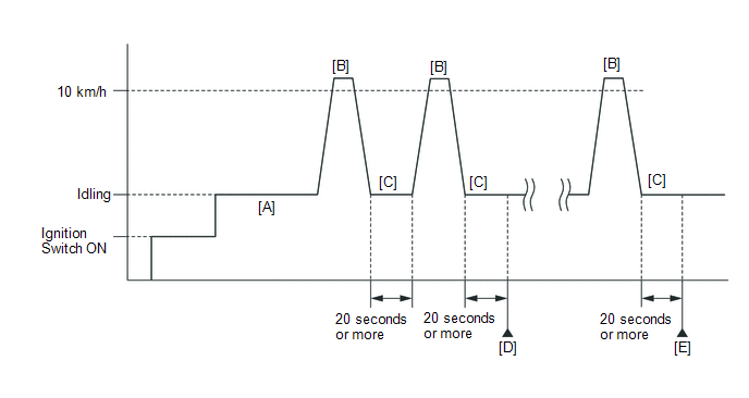
- Warm up the engine (engine coolant temperature is 80°C (176°F) or higher, air conditioning and all accessories are off) [A].
- Drive the vehicle at 10 km/h (6 mph) or more [B].
- Idle the engine for 20 seconds or more [C].
- Repeat procedure [B] and [C], and check that the idle speed
is within the specified range [D].
Standard:
Engine Idle Speed
600 to 700 rpm
HINT:
- Be sure to perform this step with all accessories off.
- Make sure that the shift lever is in P or N.
- If the idle speed is still out of the specified range, repeat procedure [B] and [C] until the idle speed is within the specified range [E].
- *4: Drive the vehicle for a short while after replacing the knock control sensor, and check if knocking occurs. If knocking occurs, drive the vehicle until knocking stops.
 Checking Monitor Status
CHECKING MONITOR STATUS
The purpose of the monitor result (mode 06) is to allow access to the results
of on-board diagnostic monitoring tests of specific components/systems that are
not continuou ...
 Problem Symptoms Table
PROBLEM SYMPTOMS TABLE
HINT:
Use the table below to help determine the cause of problem symptoms.
If multiple suspected areas are listed, the potential causes of the symptoms
are lis ...
Other materials about Toyota Venza:
Rear Height Control Sensor (B241A)
DESCRIPTION
The headlight leveling ECU assembly receives signals indicating the height of
the vehicle from the rear height control sensor sub-assembly RH.
DTC No.
DTC Detecting Condition
Trouble Area
B241A
...
Intake Manifold Runner Control Stuck Open (Bank 1) (P2004,P2006)
DESCRIPTION
The tumble control valve is built into the intake manifold. The tumble control
valve is composed of a position sensor and a DC motor. The DC motor opens and closes
the tumble control valve in response to signals from the ECM. The position sens ...
A/C ECU Vehicle Information Reading/Writing Processor Malfunction (B15F5)
DESCRIPTION
This DTC is stored when items controlled by the air conditioning amplifier assembly
cannot be customized via the navigation system vehicle customization screen.
HINT:
The air conditioning amplifier assembly controls the air conditioning system ...

0.1171