Toyota Venza: Components
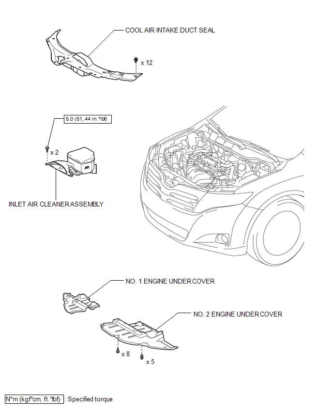
COMPONENTS
ILLUSTRATION
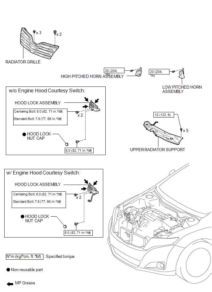
ILLUSTRATION
ILLUSTRATION
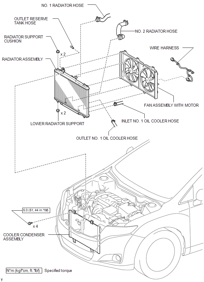
 Radiator
...
 On-vehicle Inspection
ON-VEHICLE INSPECTION
PROCEDURE
1. CHECK RADIATOR CAP SUB-ASSEMBLY
(a) Measure the valve opening pressure.
(1) If there are water stains or foreign matter on rubber packings 1, 2 or 3,
clean t ...
Other materials about Toyota Venza:
Precaution
PRECAUTION
1. NOTICE FOR INITIALIZATION:
NOTICE:
When disconnecting the cable from the negative (-) battery terminal, initialize
the following systems after the cable is reconnected.
System Name
See Procedure
Back D ...
Lost Communication with "Door Control Module B" (U0200)
DESCRIPTION
DTC No.
DTC Detection Condition
Trouble Area
U0200
No communication from the outer mirror control ECU assembly (for driver
side).
Outer mirror control ECU assem ...
Brake Switch "A" / "B" Correlation (P0504)
DESCRIPTION
The stop light switch is a duplex system that transmits 2 signals: STP and ST1-.
These 2 signals are used by the ECM to monitor whether or not the brake system is
working properly. If signals which indicate the brake pedal is being depressed a ...

0.1625