Toyota Venza: On-vehicle Inspection
ON-VEHICLE INSPECTION
CAUTION / NOTICE / HINT
CAUTION:
Be sure to follow the correct removal and installation procedures of the curtain shield airbag assembly.
PROCEDURE
1. INSPECT CURTAIN SHIELD AIRBAG ASSEMBLY (VEHICLE NOT INVOLVED IN COLLISION)
(a) Perform a diagnostic system check (See page
.gif) ).
).
(b) Visually check for defects with the curtain shield airbag assembly installed on the vehicle.
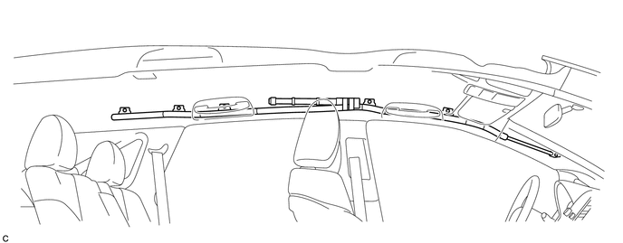
(1) The defects are as follows:
- Cuts on the front pillar garnish or roof headlining assembly around the curtain shield airbag assembly
- Small cracks on the front pillar garnish or roof headlining assembly around the curtain shield airbag assembly
- Significant discoloration on the front pillar garnish or roof headlining assembly around the curtain shield airbag assembly
OK:
No defects are found.
HINT:
If any of the defects is found, replace the front pillar garnish or roof headlining assembly with a new one.
2. INSPECT CURTAIN SHIELD AIRBAG ASSEMBLY (VEHICLE INVOLVED IN COLLISION AND AIRBAG HAS NOT DEPLOYED)
(a) Perform a diagnostic system check (See page
).
(b) Visually check for defects with the curtain shield airbag assembly removed from the vehicle.
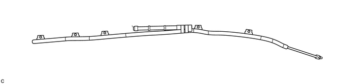
(1) The defects are as follows:
- Cuts on the curtain shield airbag assembly
- Small cracks on the curtain shield airbag assembly
- Significant discoloration on the curtain shield airbag assembly
- Cracks or other damage to the connector
OK:
No defects are found.
HINT:
If any of the defects is found, replace the curtain shield airbag assembly with a new one.
 Components
COMPONENTS
ILLUSTRATION
...
 Removal
REMOVAL
CAUTION / NOTICE / HINT
HINT:
Use the same procedure for the RH side and LH side.
The procedure listed below is for the LH side.
PROCEDURE
1. PRECAUTION
CAUTION:
Be su ...
Other materials about Toyota Venza:
Removal
REMOVAL
PROCEDURE
1. REMOVE REAR SEAT HEADREST ASSEMBLY
(a) Press the headrest support button and pull up the rear seat headrest
assembly as shown in the illustration.
2. REMOVE REAR SEAT CENTER ...
Crankshaft Position Sensor
Components
COMPONENTS
ILLUSTRATION
Removal
REMOVAL
PROCEDURE
1. REMOVE FRONT FENDER APRON SEAL RH
2. REMOVE CRANKSHAFT POSITION SENSOR
(a) Disconnect the sensor connector.
(b) Remove the bolt and sensor.
Inspection
INSPECTION
PROCEDURE ...
Precaution
PRECAUTION
1. PRECAUTION FOR DISCONNECTING THE BATTERY CABLE
NOTICE:
When disconnecting the cable from the negative (-) battery terminal, initialize
the following systems after the cable is reconnected:
System
See Procedure
...

0.1626