Toyota Venza: Components
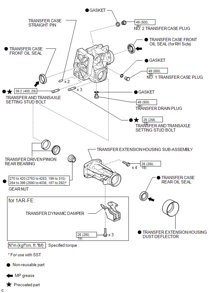
COMPONENTS
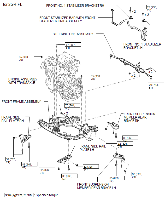
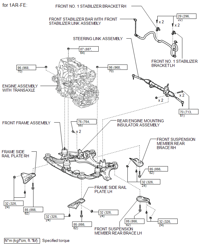
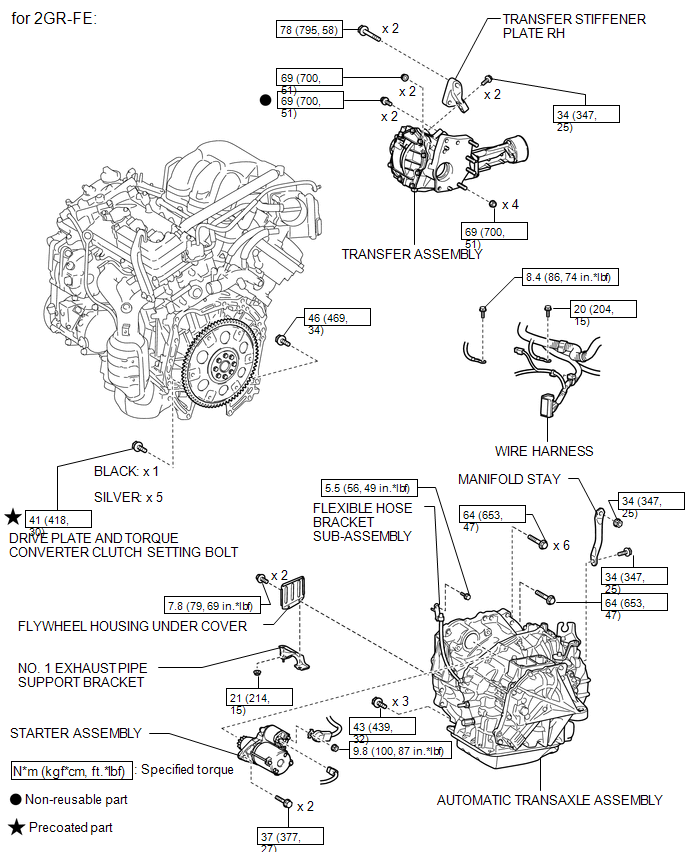
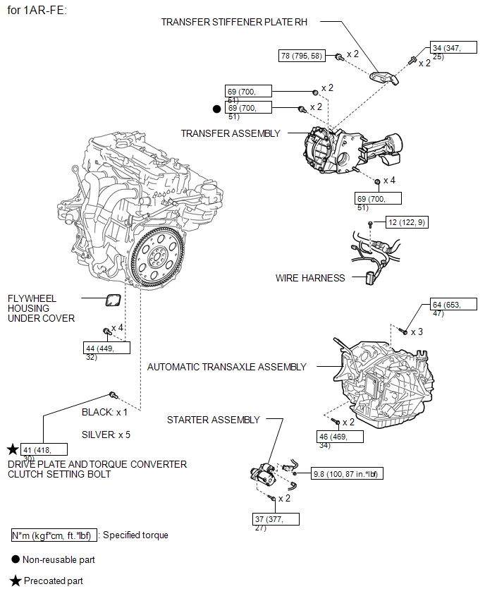
ILLUSTRATION
ILLUSTRATION
ILLUSTRATION
ILLUSTRATION
ILLUSTRATION
ILLUSTRATION


 Removal
REMOVAL
PROCEDURE
1. REMOVE ENGINE ASSEMBLY WITH TRANSAXLE
See page for 2GR-FE
See page for 1AR-FE
2. REMOVE FRONT NO. 1 STABILIZER BRACKET LH
3. REMOVE FRONT NO. 1 STABILIZER BRACKET RH
H ...
Other materials about Toyota Venza:
Installation
INSTALLATION
CAUTION / NOTICE / HINT
HINT:
Perform "Inspection After Repair" after replacing the engine assembly (See page
).
PROCEDURE
1. INSTALL IGNITION COIL ASSEMBLY
2. INSTALL FUEL DELIVERY PIPE SUB-ASSEMBLY
3. INSTALL ENGINE COOL ...
Installation
INSTALLATION
PROCEDURE
1. INSTALL NO. 1 ULTRASONIC SENSOR RETAINER
(a) Engage the 2 claws to install the No. 1 ultrasonic sensor retainer
to the rear bumper assembly.
Text in Illustration
*A
LH Side
...
Front Blower Motor
Components
COMPONENTS
ILLUSTRATION
Installation
INSTALLATION
PROCEDURE
1. INSTALL FRONT BLOWER MOTOR SUB-ASSEMBLY
(a) Install the front blower motor sub-assembly with the 3 screws.
(b) Con ...

0.1253