Toyota Venza: Components
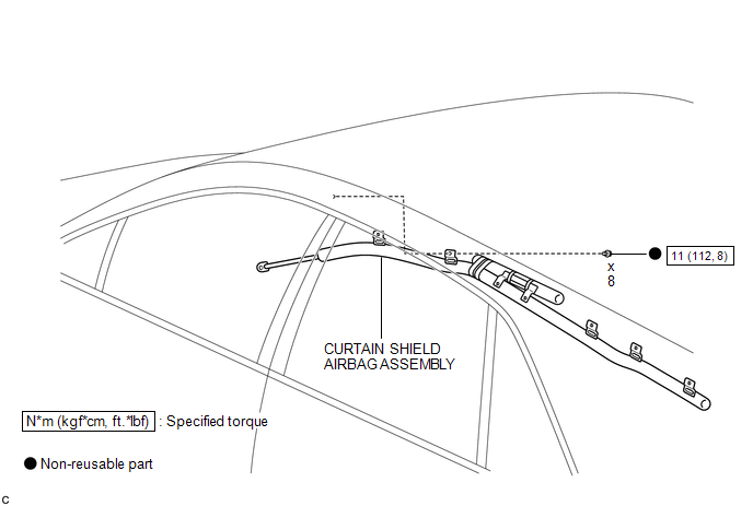
COMPONENTS
ILLUSTRATION

 On-vehicle Inspection
ON-VEHICLE INSPECTION
CAUTION / NOTICE / HINT
CAUTION:
Be sure to follow the correct removal and installation procedures of the curtain
shield airbag assembly.
PROCEDURE
1. INSPECT CURTAIN SHIE ...
Other materials about Toyota Venza:
How To Proceed With Troubleshooting
CAUTION / NOTICE / HINT
HINT:
Use the following procedures to troubleshoot the power back door system.
*: Use the Techstream.
PROCEDURE
1.
VEHICLE BROUGHT TO WORKSHOP
NEXT
...
Driver Side Door Entry Lock Function does not Operate
DESCRIPTION
If the driver door entry unlock function operates normally, but its entry lock
function does not, this means that the request code from the driver door is being
output normally. In this case, a malfunction in the lock sensor circuit (from the ...
Removal
REMOVAL
PROCEDURE
1. REMOVE FUEL SUCTION TUBE ASSEMBLY WITH PUMP AND GAUGE
(a) Remove the fuel suction tube assembly with pump and gauge (See page
).
2. REMOVE FUEL SENDER GAUGE
3. REMOVE FUEL FILTER ASSEMBLY
(a) Disconnect the fuel pump ...

0.1367