Toyota Venza: On-vehicle Inspection
ON-VEHICLE INSPECTION
PROCEDURE
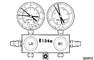
1. INSPECT REFRIGERANT PRESSURE WITH MANIFOLD GAUGE SET
HINT:
This is a method where a manifold gauge set is used to help locate the problem.
(a) Read the manifold gauge pressure when the following conditions are met:
Test conditions:
- Temperature at the air inlet with the switch set at RECIRC is 30 to 35°C (86 to 95°F).
- The engine is running at 1500 rpm.
- The blower speed control switch position is at "HI".
- The temperature control dial position is at "COOL".
- The A/C switch is on.
- Doors are fully open.
- The ignition switch is in a position that enables the A/C compressor to run.
|
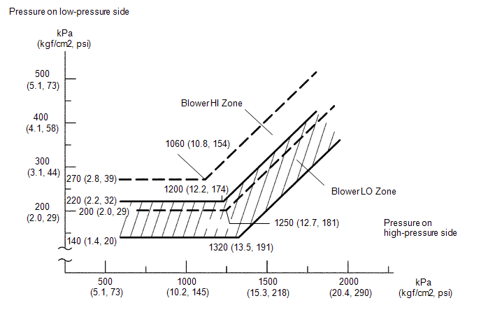
(1) Normally functioning refrigeration system Gauge Reading
|
|
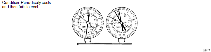
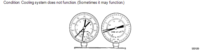
(2) Moisture is present in the refrigeration system.
|
Symptom |
Probable Cause |
Diagnosis |
Corrective Action |
|---|---|---|---|
|
During operation, pressure on low pressure side cycles between normal and vacuum |
|
|
|
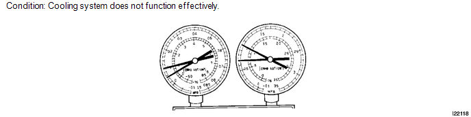
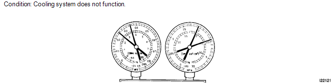
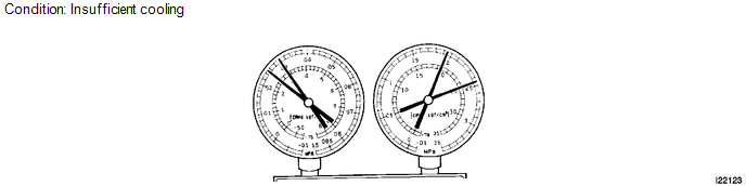
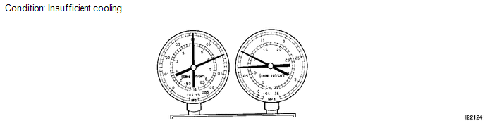
(3) Insufficient cooling
|
Symptom |
Probable Cause |
Diagnosis |
Corrective Action |
|---|---|---|---|
|
Gas leaks from the refrigeration system |
|
|
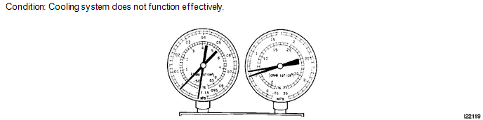
(4) Poor circulation of refrigerant
|
Symptom |
Probable Cause |
Diagnosis |
Corrective Action |
|---|---|---|---|
|
Refrigerant flow is obstructed by dirt inside the pipes of the condenser core |
Receiver is clogged |
Replace condenser |
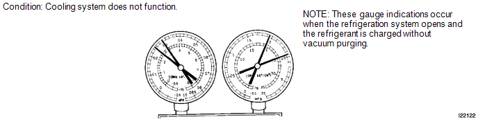
(5) Refrigerant does not circulate.
|
Symptom |
Probable Cause |
Diagnosis |
Corrective Action |
|---|---|---|---|
|
|
Refrigerant does not circulate |
|
(6) Refrigerant is overcharged or cooling effectiveness of condenser is insufficient.
|
Symptom |
Probable Cause |
Diagnosis |
Corrective Action |
|---|---|---|---|
|
|
|
|
(7) Air is present in the refrigeration system.
|
Symptom |
Probable Cause |
Diagnosis |
Corrective Action |
|---|---|---|---|
|
Air in system |
|
|
(8) Expansion valve malfunction
|
Symptom |
Probable Cause |
Diagnosis |
Corrective Action |
|---|---|---|---|
|
Expansion valve may be stuck |
|
Check expansion valve |
(9) Insufficient compressor compression
|
Symptom |
Probable Cause |
Diagnosis |
Corrective Action |
|---|---|---|---|
|
Internal leak in compressor |
|
Replace compressor |
Gauge readings (Reference)
 Refrigerant
...
 Replacement
REPLACEMENT
PROCEDURE
1. RECOVER REFRIGERANT FROM REFRIGERATION SYSTEM
(a) Start up the engine.
(b) Turn the A/C switch on.
(c) Operate the cooler compressor at an engine speed of approximately 1 ...
Other materials about Toyota Venza:
Reassembly
REASSEMBLY
PROCEDURE
1. INSTALL NO. 1 SUNSHADE TRIM SUB-ASSEMBLY
(a) Slide and install the No. 1 sunshade trim sub-assembly.
2. INSTALL NO. 2 SUNSHADE TRIM SUB-ASSEMBLY
(a) Slide and ins ...
Speed Sensor(when Not Using The Engine Support Bridge)
Components
COMPONENTS
ILLUSTRATION
Removal
REMOVAL
PROCEDURE
1. REMOVE AUTOMATIC TRANSAXLE ASSEMBLY
HINT:
See the steps from "Remove Engine Assembly with transaxle" through "Remove Automatic
Transaxle Assembly" (See page ). ...
How To Proceed With Troubleshooting
CAUTION / NOTICE / HINT
HINT:
Use the following procedure to troubleshoot the power window control
system.
*: Use the Techstream.
PROCEDURE
1.
VEHICLE BROUGHT TO WORKSHOP
NEXT
...

0.1535