Toyota Venza: Accelerator Pedal
Components
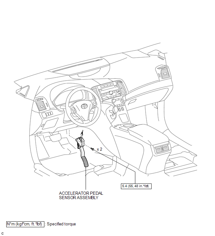
COMPONENTS
ILLUSTRATION
On-vehicle Inspection
ON-VEHICLE INSPECTION
PROCEDURE
1. INSPECT ACCELERATOR PEDAL SENSOR ASSEMBLY
(a) Connect the Techstream to the DLC3.
(b) Turn the ignition switch to ON.
(c) Turn the Techstream on.
(d) Enter the following menus: Powertrain / Engine / Data List / Accel Sensor Out No. 1 and Accel Sensor Out No. 2.
(e) Read the values displayed on the Techstream.
Standard Voltage:
|
Tester Display |
Condition |
Specified Condition |
|---|---|---|
|
Accel Sensor Out No. 1 |
Accelerator pedal is released |
0.5 to 1.1 V |
|
Accelerator pedal is fully depressed |
2.6 to 4.5 V |
|
|
Accel Sensor Out No. 2 |
Accelerator pedal is released |
1.2 to 2.0 V |
|
Accelerator pedal is fully depressed |
3.4 to 4.75 V |
If the result is not as specified, check the accelerator pedal sensor assembly, wire harness or ECM.
Installation
INSTALLATION
PROCEDURE
1. INSTALL ACCELERATOR PEDAL SENSOR ASSEMBLY
NOTICE:
- Avoid physical shock to the accelerator pedal sensor assembly.
- Do not disassemble the accelerator pedal sensor assembly.
- The accelerator pedal sensor assembly does not require lubrication.
- Do not apply oil or other lubricants to the accelerator pedal sensor assembly. If applied, the accelerator pedal sensor assembly must be replaced.
|
(a) Install the accelerator pedal sensor assembly with the 2 bolts. Torque: 5.4 N·m {55 kgf·cm, 48 in·lbf} |
|
(b) Connect the accelerator pedal sensor assembly connector.
Removal
REMOVAL
PROCEDURE
1. REMOVE ACCELERATOR PEDAL SENSOR ASSEMBLY
NOTICE:
- Avoid physical shock to the accelerator pedal sensor assembly.
- Do not disassemble the accelerator pedal sensor assembly.
- The accelerator pedal sensor assembly does not require lubrication.
- Do not apply oil or other lubricants to the accelerator pedal sensor assembly. If applied, the accelerator pedal sensor assembly must be replaced.
|
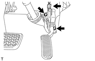
(a) Disconnect the accelerator pedal sensor assembly connector. |
|
.png)
(b) Remove the 2 bolts and accelerator pedal sensor assembly.

 Air Fuel Ratio Sensor
Components
COMPONENTS
ILLUSTRATION
Removal
REMOVAL
PROCEDURE
1. REMOVE NO. 1 ENGINE COVER SUB-ASSEMBLY
2. REMOVE COOL AIR INTAKE DUCT SEAL
3. REMOVE INLET AIR CLEANER ASSEMBLY
...
Other materials about Toyota Venza:
Terminals Of Ecu
TERMINALS OF ECU
1. CHECK POWER BACK DOOR ECU (POWER BACK DOOR MOTOR UNIT)
(a) Disconnect the L20 ECU connector.
(b) Measure the voltage and resistance according to the value(s) in the table
below.
Tester Connection
Wiring Color
...
Height Control Sensor
Components
COMPONENTS
ILLUSTRATION
ILLUSTRATION
Removal
REMOVAL
PROCEDURE
1. REMOVE REAR HEIGHT CONTROL SENSOR SUB-ASSEMBLY (for 2WD)
(a) Disconnect the connector.
(b) Remove the 3 nuts ...
Back Door Closer does not Operate
DESCRIPTION
When the back door closer does not operate, one of the following may be the cause:
1) improper fit of the back door, or a foreign object is stuck in the back door
or 2) initialization of the power back door ECU (power back door motor unit)*1, ...

0.1742