
Toyota Venza: Installation
INSTALLATION
PROCEDURE
1. INSTALL DRIVER SIDE KNEE AIRBAG ASSEMBLY
(a) Check that the ignition switch is off.
(b) Check that the cable is disconnected from the negative (-) battery terminal.
CAUTION:
Wait at least 90 seconds after disconnecting the cable from the negative (-) battery terminal to disable the SRS system.
|
(c) Connect the driver side knee airbag connector to the driver side knee airbag assembly. Text in Illustration
NOTICE: When connecting the airbag connector, take care not to damage the airbag wire harness. |
|
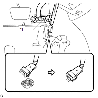
(d) Connect the DLC3 to the driver side knee airbag assembly with the 2 claws.
|
(e) Temporarily install the driver side knee airbag assembly with the 2 hooks. |
|
.png)
(f) Install the driver side knee airbag assembly with the 4 bolts.
Torque:
10 N·m {102 kgf·cm, 7 ft·lbf}
2. INSTALL LOWER NO. 1 INSTRUMENT PANEL FINISH PANEL
.gif)
3. INSTALL COWL SIDE TRIM SUB-ASSEMBLY LH
4. INSTALL FRONT DOOR SCUFF PLATE LH
5. CONNECT CABLE TO NEGATIVE BATTERY TERMINAL
NOTICE:
When disconnecting the cable, some systems need to be initialized after the cable
is reconnected (See page ).
6. PERFORM DIAGNOSTIC SYSTEM CHECK
(a) Perform a diagnostic system check (See page
).
7. INSPECT SRS WARNING LIGHT
(a) Inspect the SRS warning light (See page
).
 Disposal
DISPOSAL
CAUTION / NOTICE / HINT
CAUTION:
Before performing pre-disposal deployment of any SRS component, review and closely
follow all applicable environmental and hazardous material regulations ...
 Occupant Classification Ecu
Components
COMPONENTS
ILLUSTRATION
ILLUSTRATION
On-vehicle Inspection
ON-VEHICLE INSPECTION
CAUTION / NOTICE / HINT
CAUTION:
Be sure to follow the correct removal and installation proc ...
Other materials about Toyota Venza:
Removal
REMOVAL
PROCEDURE
1. REMOVE FRONT SEAT HEADREST ASSEMBLY
2. REMOVE FRONT SEAT REAR OUTER TRACK COVER
3. REMOVE FRONT SEAT REAR INNER TRACK COVER
4. REMOVE FRONT SEAT ASSEMBLY
5. REMOVE RECLINING POWER SEAT SWITCH KNOB
6. REMOVE SLIDE AND VER ...
IG2 Signal Malfunction (B2788)
DESCRIPTION
The steering lock ECU (steering lock actuator assembly) receives power from the
IG2 relay. When the voltage value indicated by the IG signal from the certification
ECU (smart key ECU assembly) equals to the voltage that is applied to the steer ...
Torque Sensor Zero Point Adjustment Undone (C1515,C1525)
DESCRIPTION
These DTCs do not indicate a malfunction. The power steering ECU stores these
DTCs when it determines that the rotation angle sensor value initialization and
torque sensor zero point calibration have not been performed.
DTC No.
...

0.1193